Video and Audio Processing
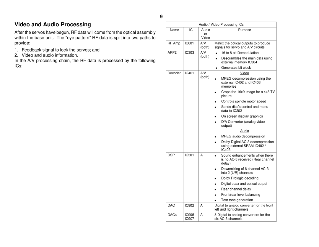
After the servos have begun, RF data will come from the optical assembly within the base unit. The “eye pattern” RF data is split into two paths to provide:
1.Feedback signal to lock the servos; and
2.Video and audio information.
In the A/V processing chain, the RF data is processed by the following ICs:
9
Audio / Video Processing ICs
Name | IC | Audio |
| Purpose |
|
| or |
|
|
|
| Video |
|
|
|
|
|
| |
RF Amp | IC001 | A/V | Matrix the optical outputs to produce | |
|
| (both) | signals for servo and A/V circuits | |
|
|
|
|
|
ARP2 | IC303 | A/V | ∙ | 16 to 8 bit Demodulation |
|
| (both) | ∙ | Descrambles the main data using |
|
|
| ||
|
|
|
| external memory IC304 |
|
|
| ∙ | Generates bit clock |
|
|
|
|
|
Decoder | IC401 | A/V |
| Video |
|
| (both) | ∙ | MPEG decompression using the |
|
|
| ||
|
|
|
| external IC402 and IC403 |
|
|
|
| memories |
|
|
| ∙ | Crops the 16x9 image for a 4x3 TV |
|
|
|
| picture |
|
|
| ∙ | Controls spindle motor speed |
|
|
| ∙ | Sends disc’s control and menu |
|
|
|
| data to IC202 |
|
|
| ∙ | On screen display graphics |
|
|
| ∙ | D/A Converter (analog video |
|
|
|
| output) |
|
|
|
| Audio |
|
|
| ∙ | MPEG audio decompression |
|
|
| ∙ | Dolby Digital |
|
|
|
| using external SRAM IC402 / |
|
|
|
| IC403 |
|
|
|
|
|
DSP | IC501 | A | ∙ | Sound enhancements when there |
|
|
|
| is no |
|
|
|
| delay) |
|
|
| ∙ | Downmixing of 6 channel |
|
|
|
| into 2 (L/R) channels |
|
|
| ∙ | Dolby Prologic decoding |
|
|
| ∙ | Digital coax and optical output |
|
|
| ∙ | Rear channel delay |
|
|
| ∙ | Front/rear level balancing |
|
|
| ∙ | Test tone generation |
|
|
|
| |
DAC | IC902 | A | Digital to analog converter for the front | |
|
|
| left and right channels | |
|
|
|
| |
DACs | IC905- | A | 3 Digital to analog converters for the | |
| IC907 |
| six | |
|
|
|
|
|