Audio/Video Processing Block
The RF / eye pattern signal is processed by several blocks to recover the audio and video signal that is output the rear panel.
Optical Device
The optical device contains an active amplifier and matrix to produce a low noise RF or eye pattern signal from the
RF Amplifier IC001
The RF signal is amplified when small, and limited when large, to equalize the eye pattern signal that is applied to the next A/V stage. The
ARP2 IC303
The Advanced RF Processor (ARP2) IC303 receives the analog eye pat- tern data and first converts it into a digital waveform by “slicing” it across the middle. A voltage above the middle becomes a HIGH output and a voltage below becomes a LOW voltage. The HIGH and LOW voltage begin their digital journey within IC303. To support the digital signal a clock is made from the input signal.
How successful the data locks to the internal PLL to make this clock can be monitored at the JITTER pin 57 of IC303. A low voltage proves a lock. This means the servos are OK and the signal processing is OK to this point. A high voltage means the input eye pattern should be examined again. A clear (no noise) signal means the servos are OK and the disc signal is incorrect or IC303 is not able to lock onto the input signal (IC303 or its support parts are defective).
Additional signal processing within IC303 unscrambles the digital data and channels the CD and DVD data into separate output ports. Both outputs are fed to separate A/V Decoder IC401 inputs.
73
A/V Decoder IC401
The CD and DVD input signals undergo separate processing. The CD audio is virtually untouched and leaves the IC in the audio processing path to IC501.
The DVD video signal is MPEG decompressed using two external SDRAM ICs (not shown) for momentary storage during the processing. The subpicture (subtitle and DVD disc menu) pieces of data are loaded into memory and when called for, added into the main picture. The digital information is returned to analog form by the internal D/A converter. The DVD player’s menu is added as an on screen display (OSD) just before the analog video leaves IC401.
The DVD audio signal is also MPEG decompressed and the PCM is ex- tracted to take the route out of IC401 through IC501 and IC902 for the analog audio processing. Dolby digital
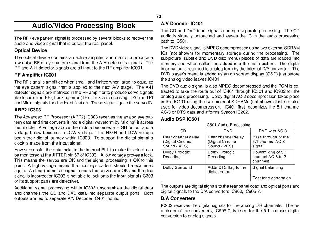
Audio DSP IC501
IC501 Audio Processing
CD | DVD | DVD with |
|
|
|
Rear channel delay | Rear channel delay | Pass through of the |
(Digital Cinema | (Digital Cinema | 5.1 channel |
Sound / VES) | Sound / VES) | signal |
|
|
|
Dolby Prologic | Dolby Prologic | Downmixing of 5.1 |
Decoding | Decoding | channel |
|
| channels. |
|
|
|
Dolby Surround | Adds DTS flag to the | Signal balancing |
| digital output |
|
|
|
|
|
| Test tone generation |
|
|
|
The outputs are digital signals to the rear panel coax and optical ports and digital signals to the D/A converters IC902,
D/A Converters
IC902 receives the digital signals for the analog L/R channels. The re- mainder of the converters,