IC601 and IC701 Communications
| Name | From IC | When Present |
|
|
|
|
1. | Chip | System Control IC202 | Power on/off, playback, tray |
| Select |
| open close, and start/stop.. |
|
|
|
|
2. | Read | System Control IC202 | Always when powered on |
|
|
|
|
3. | Write | System Control IC202 | Completion of command |
|
|
| (PB, pause, pwr on/off) |
|
|
|
|
4. | Interrupt | Servo IC701 | Completion of command |
|
|
| (PB, pause, pwr on/off) |
|
|
| |
Address | Always when powered on | ||
|
|
| |
Data | Always when powered on | ||
|
|
|
|
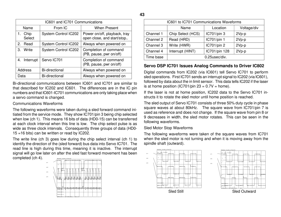
Communications Waveforms
The following waveforms were taken during a sled forward command ini- tiated from the service mode. They show IC701/pin 3 being chip selected when low (ch 1). This means 16 bits of data
The write line (ch 3) goes low during the chip select interval (ch 1) to identify the direction of the (sled forward) bus data into Servo IC701. The read line is high during this time, meaning it is inactive. The interrupt signal will go low later on after the sled fast forward movement has been completed (ch 4).
ch1
ch2
1
ch3
ch4
2
3
CH1!2 . 00 V=
CH2!2 . 00 V=
43
IC601 to IC701 Communications Waveforms
| Name | Location | Voltage/div |
|
|
|
|
Channel 1 | Chip Select (HCS) | IC701/pin 3 | |
|
|
|
|
Channel 2 | Read (HRD) | IC701/pin 1 | |
|
|
|
|
Channel 3 | Write (HWR) | IC701/pin 2 | |
|
|
|
|
Channel 4 | Interrupt (HINT) | IC701/pin 128 | |
|
|
|
|
Time base |
| 0.25usec/div. |
|
|
|
|
|
Servo DSP IC701 Issues Analog Commands to Driver IC802
Digital commands from IC202 (via IC601) tell Servo IC701 to perform sled operations. First IC701 sends an interrupt signal to IC202 (via IC601), followed by data about the in limit sensor. This data tells IC202 if the laser is at home position (IC701/pin 23 = 0.7V = home).
If the laser is not at home position, IC202 data to the Servo IC701 in- structs it to rotate the sled motor until home position is reached.
The sled output of Servo IC701 consists of three 50% duty cycle in phase square waves at about 80kHz. The square wave from IC701/pin 7 is used as reference and does not change. If the square wave from pin 8 or 9 decreases in width, the sled motor rotates. This can be seen in the following waveforms.
Sled Motor Stop Waveforms
The following waveforms were taken of the square waves from IC701 when the sled motor is not turning and when it is moving away from the spindle shaft (outward).
| P M 3 3 9 4 , F L U K E & P H I L I P S |
|
| P M 3 3 9 4 , F L U K E & P H I L I P S |
|
| ch1: freq= 79 . 4kHz |
|
| ch1: freq= 79 . 4kHz |
|
ch1 |
|
|
|
| |
|
| ch1 |
|
| |
|
|
|
|
| |
ch2 | T |
| ch2 | T |
|
|
|
| |||
|
|
|
|
| |
ch3 | 1 |
|
| 1 |
|
|
| ch3 |
| ||
|
|
|
| ||
|
|
|
|
| |
| 2 |
|
| 2 |
|
|
|
|
|
| |
| CH1!2 . 00 V= |
|
| CH1!2 . 00 V= |
|
|
|
|
|
| |
| CH2!2 . 00 V= |
|
| 3CH2!2 . 00 V= |
|
| 3 |
|
|
| |
| CH3!2 . 00 V= ALT MTB5 . 00us | ch1+ |
| CH3!2 . 00 V= ALT MTB5 . 00us | ch1+ |
| Sled Still |
| Sled Outward | ||
CH3!2 . 00 V=
CH4!2 . 00 V= ALT MTB 250ns - 1 . 06dv ch1 -