31
Mechanism
Disc Tray and Laser Platform Position
Tray Movement
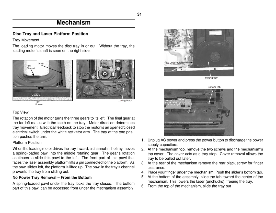
The loading motor moves the disc tray in or out. Without the tray, the loading motor’s shaft is seen on the right side.
Teeth
Pawl
Channel
Tab underneath ![]()
Mechanism
Bottom Tab
Tray
Bottom
Top View
Loading Motor
The rotation of the motor turns the three gears to its left. The final gear at the
Platform Position
When the loading motor drives the tray inward, a channel in the tray moves a
No Power Tray Removal – From the Bottom
A
1.Unplug AC power and press the power button to discharge the power supply capacitors.
2.At the mechanism top, remove the two screws and the mechanism’s top cover. The cover acts as a tray stop. Cover removal allows the tray to be pulled out later.
3.At the rear of the mechanism remove the rear black screw for finger clearance.
4.Place your finger under the mechanism. Push the slider’s bottom tab.
5.At the bottom of the assembly, slide the tab toward the center of the mechanism. This lowers the laser (unchucks), freeing the tray.
6.From the top of the mechanism, slide the tray out