Tilt Drive– Test Mode Tilt Down
| Name | Location | Voltage/div |
|
|
|
|
Channel 1 | TLTB | IC701/pin 48 | |
|
|
|
|
Channel 2 | TLTA | IC701/pin 49 | |
|
|
|
|
Channel 3 | ITA - | CN003/pin 1 | |
|
|
|
|
Channel 4 | ITA + | CN003/pin 2 |
|
|
|
|
|
Time base |
| 500msec/div. |
|
|
|
|
|
Driver IC801 supplies the current necessary to develop the magnetic fields in the motor to make it step. The tilt motor driver IC801 is inhibited (muted) from working when the tray is out when a low is placed at IC801/pin 20.
DVD Playback
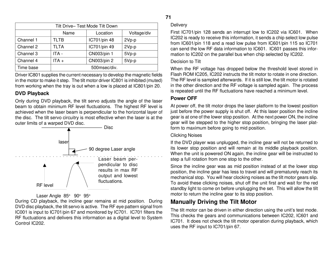
Only during DVD playback, the tilt servo adjusts the angle of the laser beam to obtain minimum RF level fluctuations. The highest RF level is achieved when the laser beam is perpendicular to the horizontal layer of the disc. The tilt servo circuitry is most effective when the laser is at the
outer limits of a warped DVD disc.
Disc
laser
![]() 90 degree Laser angle
90 degree Laser angle
Laser beam per- pendicular to disc results in max RF output and lowest
fluctuations.
RF level
Laser Angle 85o 90o 95o
During CD playback, the incline gear remains at mid position. During DVD disc playback, the tilt servo is active. The RF eye pattern signal from IC001 is input to IC701/pin 67 and monitored by IC701. IC701 filters the RF fluctuations and delivers this information as a digital level to System Control IC202.
71
Delivery
First IC701/pin 128 sends an interrupt low to IC202 via IC601. When IC202 is ready to receive this information, it sends a chip select low pulse from IC601/pin 118 and a read low pulse from IC601/pin 115 so IC701 can send the low RF data information to IC601. IC601 passes this infor- mation to IC202 on the parallel bus when chip selected by IC202.
Decision to Tilt
When the RF voltage has dropped below the threshold level stored in Flash ROM IC205, IC202 instructs the tilt motor to rotate in one direction. The RF level is sampled afterwards. If it is still low, the tilt motor is rotated in the other direction and the RF voltage is sampled again. The process is repeated until the RF fluctuations have reached a minimum level.
Power OFF
At power off, the tilt motor drops the laser platform to the lowest position just before the power supply is shut off. At this laser position the incline gear is at one of the lower stop position. At the next power ON, the incline gear will be stepped to the higher stop position, bringing the laser plat- form to maximum before going to mid position.
Clicking Noises
If the DVD player was unplugged, the incline gear will not be returned to its lower stop position and will remain at its middle playback position. When the unit is powered ON again, the incline gear will be instructed to step a full rotation from one stop to the other.
Since the incline gear was as mid position instead of at the lower stop position, the incline gear has less to travel and will prematurely reach its mechanical stop. You will hear clocking noises as the tilt motor gears slip. To avoid these clicking noises, shut off the unit first and wait for the red standby light to come on before unplugging the set. This will allow the tilt motor to return the incline gear to its stop position.
Manually Driving the Tilt Motor
The tilt motor can be driven in either direction using the unit’s test mode. This checks the gears and communications between IC202, IC601 and IC701. It does not check the tilt motor operation during playback, which uses the RF input to IC701/pin 67.