Power Control
Plug In
When the DVD player is plugged into AC, the power supply only outputs Ever 5V to:
·Analog audio mute transistors –
·Interface IC201/pin 16 – FL101 board
·Reset IC202/pin 5 - FL101 board
The mute transistors are biased ON to keep the 5.1, headphones and L/ R channel audio outputs grounded.
Ever 5V applied to Interface IC201 starts the 4MHz X201 crystal con- nected to pins 14 and 15.
Reset IC202 on the FL101 board uses C211 to hold its pin 4 momentarily low when Ever 5V is first applied. This resets Interface IC201/pin 18.
After reset, a brief communication occurs between IC201 and IC202. A momentary light of the front panel blue Dolby Digital LED (D203) marks the end of the plug in communications and the unit shuts down.
The plug in sequence is listed below:
1.AC plug in
2.Ever 5V is applied to Interface IC201/pin 16
3.X201 becomes active and stays active
4.Red power off/standby LED comes ON.
5.PCONT from Interface IC201/pin 24 goes high to power the set
6.Ready pulse is output IC201/pin 78 as an interrupt line to IC202 to begin communications. It is difficult to see this low going interrupt pulse on a a scope, but it will light a scope’s “triggered” LED.
7.IC601 transfers this “ready” (interrupt) information to System Control IC202 by using another interrupt signal from IC601/pin 155 (low go- ing). The low forces IC202 to generate a chip select (CS1 or CS4) so the data can be transferred to IC202 on the parallel bus.
8.System Control IC202 sends chip select (difficult to see the low going pulse from pin 97), bit clock (low pulses from pin 78) and serial data (high pulses from pin 77) to Interface IC201.
9.IC201 acknowledges by lighting the Digital Dolby LED D203
17
10.Interface IC201 brings PCONT low, removing power to the set. Unit is now in standby and ready to be powered ON.
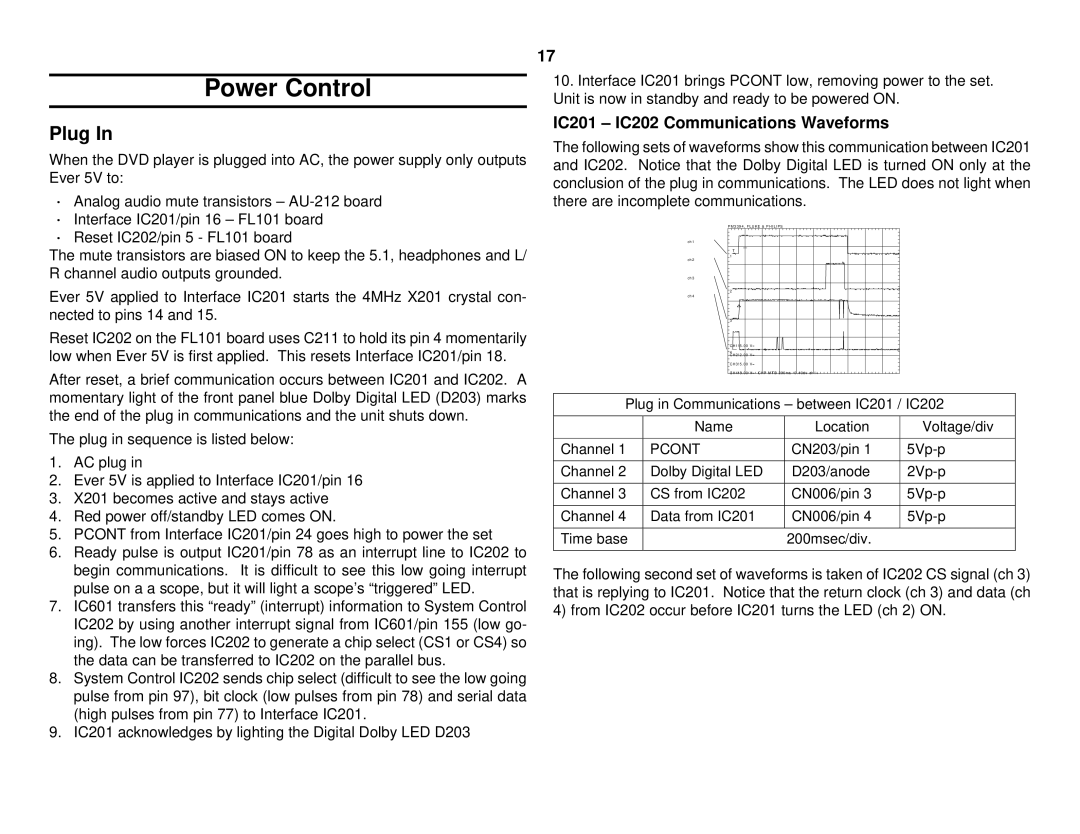
IC201 – IC202 Communications Waveforms
The following sets of waveforms show this communication between IC201 and IC202. Notice that the Dolby Digital LED is turned ON only at the conclusion of the plug in communications. The LED does not light when there are incomplete communications.
P M 3 3 9 4 , F L U K E & P H I L I P S
ch1
T
1
ch2
ch3
2
ch4
3
CH1!5 . 00 V=
4
CH2!2 . 00 V=
CH3!5 . 00 V=
CH4!5 . 00 V= CHP MTB 200ms - 0 . 40dv ch1+
Plug in Communications – between IC201 / IC202
| Name | Location | Voltage/div |
|
|
|
|
Channel 1 | PCONT | CN203/pin 1 | |
|
|
|
|
Channel 2 | Dolby Digital LED | D203/anode | |
|
|
|
|
Channel 3 | CS from IC202 | CN006/pin 3 | |
|
|
|
|
Channel 4 | Data from IC201 | CN006/pin 4 | |
|
|
|
|
Time base |
| 200msec/div. |
|
|
|
|
|
The following second set of waveforms is taken of IC202 CS signal (ch 3) that is replying to IC201. Notice that the return clock (ch 3) and data (ch 4) from IC202 occur before IC201 turns the LED (ch 2) ON.