Tray Motor Drive
The opening and closing of the disc tray involves two micro controllers, one gate array IC and a driver IC that powers the loading motor. The loading motor is powered by pressing the front panel open/close tray but- ton S212. The following occurs when the tray button is pressed:
1.Interface Controller IC201 recognizes the tray button
2.IC201 turns on the display to show the command entered
3.IC201 communicates with System Control IC202
4.IC202 instructs Hybrid gate array IC601 to issue a drive command
5.Driver IC802 translates the command into loading motor current
6.The tray position switch returns information to IC201 (via IC601) The tray position switch information is sent to Interface IC201 via IC202 to complete the tray open cycle. The “OPEN” display disappears when the cycle is complete. This also sets the latch, permitting the tray to be closed the next time the tray button is pressed.
37
2.IC601 sends this information along the parallel bus to IC202. This occurs when IC601/pin 142 is periodically (chip) selected using CS1 or CS4 to send and receive data. Two chip select lines are used in different parts of the Hybrid Gate Array IC601.
3.When IC202 is ready, it outputs a low chip select signal (ch 4) from pin 97 to Interface IC201/pin 76. IC203,
4.IC202 simultaneously sends serial clock from pin 78 to IC201/pin 70 (ch 3) during the chip select interval.
5.Data is transmitted from IC201/pin 71 to IC202/pin 76 (ch 2).
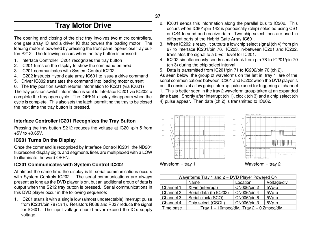
As seen below, the group of waveforms on the left in “tray 1” are of the serial communications between IC201 and IC202 when the DVD player is on. It consists of a low going interrupt pulse used for triggering at channel
1.This is better seen in the tray 2 waveform group taken at an expanded time base. Shortly after interrupt (ch 1), clock (ch 3) and a chip select (ch 4) pulse appear. Then data (ch 2) is transmitted to IC202.
PM3394, FLUKE & PHILIPS | PM3394, FLUKE & PHILIPS |
Interface Controller IC201 Recognizes the Tray Button
Pressing the tray button S212 reduces the voltage at IC201/pin 5 from +5V to +0.65V.
IC201 Turns On the Display
Once the command is recognized by Interface Control IC201, the ND201 fluorescent display digits and segments lines are multiplexed with a LOW to illuminate the word OPEN.
IC201 Communicates with System Control IC202
At almost the same time the display is lit, serial communications occurs with System Controls IC202. The serial communications are always present as long as the DVD player is on, but an additional group of data is output when the S212 tray button is pressed. Serial communications in this DVD player occur in the following sequence:
1.IC201 starts it with a single low (almost undetectable) interrupt pulse from IC201/pin 78 (ch 1). Resistors R036 and R037 reduce the signal for IC601. The input voltage should never exceed the IC’s supply voltage.
ch1 |
|
| ch1 |
|
| T |
| T |
|
| 1 |
| 1 |
|
ch2 |
|
| ch2 |
|
ch3 |
|
| ch3 |
|
ch4 | 2 |
| ch4 |
|
|
| 2 |
| |
| =A G |
| 3 |
|
| 3 |
|
| |
| CH1!5.00 V= |
| CH1!5.00 V= |
|
| CH2!5.00 V= |
| CH2!5.00 V= |
|
| 4 |
| 4 |
|
| CH3!5.00 V= |
| CH3!5.00 V= |
|
| CH4!5.00 V= | CHP MTB10.0ms- 0.72dv ch1- | CH4!5.00 V= CHP MTB 200us- 0.72dv ch1- | |
Waveform = tray 1 | Waveform = tray 2 | |||
| Waveforms Tray 1 and 2 = DVD Player Powered ON | |||
|
| Name | Location | Voltage/div |
Channel 1 | XIFint(interrupt) | CN006/pin 2 | ||
Channel 2 Serial data (to IC202) | CN006/pin 4 | |||
Channel 3 Serial clock (SCO) | CN006/pin 6 | |||
Channel 4 Chip select (CSOL) | CN006/pin 3 | |||
Time base | Tray 1 = 10msec/div. Tray 2 = 0.2msec/div | |||