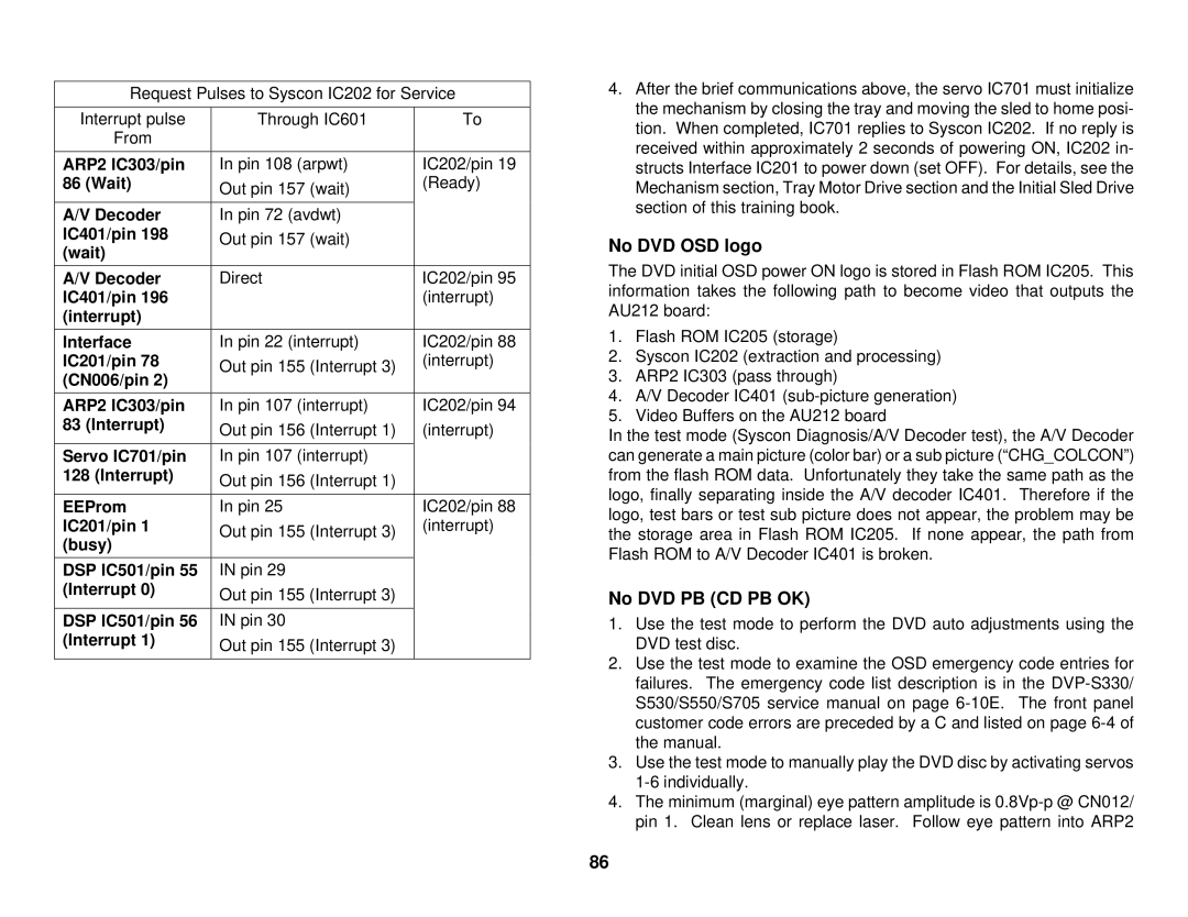
Request Pulses to Syscon IC202 for Service
Interrupt pulse | Through IC601 | To |
From |
|
|
|
|
|
ARP2 IC303/pin | In pin 108 (arpwt) | IC202/pin 19 |
86 (Wait) | Out pin 157 (wait) | (Ready) |
|
| |
|
|
|
A/V Decoder | In pin 72 (avdwt) |
|
IC401/pin 198 | Out pin 157 (wait) |
|
(wait) |
| |
|
| |
|
|
|
A/V Decoder | Direct | IC202/pin 95 |
IC401/pin 196 |
| (interrupt) |
(interrupt) |
|
|
|
|
|
Interface | In pin 22 (interrupt) | IC202/pin 88 |
IC201/pin 78 | Out pin 155 (Interrupt 3) | (interrupt) |
(CN006/pin 2) |
| |
|
| |
|
|
|
ARP2 IC303/pin | In pin 107 (interrupt) | IC202/pin 94 |
83 (Interrupt) | Out pin 156 (Interrupt 1) | (interrupt) |
| ||
|
|
|
Servo IC701/pin | In pin 107 (interrupt) |
|
128 (Interrupt) | Out pin 156 (Interrupt 1) |
|
|
| |
|
|
|
EEProm | In pin 25 | IC202/pin 88 |
IC201/pin 1 | Out pin 155 (Interrupt 3) | (interrupt) |
(busy) |
| |
|
| |
|
|
|
DSP IC501/pin 55 | IN pin 29 |
|
(Interrupt 0) | Out pin 155 (Interrupt 3) |
|
|
| |
|
|
|
DSP IC501/pin 56 | IN pin 30 |
|
(Interrupt 1) | Out pin 155 (Interrupt 3) |
|
|
| |
|
|
|
4.After the brief communications above, the servo IC701 must initialize the mechanism by closing the tray and moving the sled to home posi- tion. When completed, IC701 replies to Syscon IC202. If no reply is received within approximately 2 seconds of powering ON, IC202 in- structs Interface IC201 to power down (set OFF). For details, see the Mechanism section, Tray Motor Drive section and the Initial Sled Drive section of this training book.
No DVD OSD logo
The DVD initial OSD power ON logo is stored in Flash ROM IC205. This information takes the following path to become video that outputs the AU212 board:
1.Flash ROM IC205 (storage)
2.Syscon IC202 (extraction and processing)
3.ARP2 IC303 (pass through)
4.A/V Decoder IC401
5.Video Buffers on the AU212 board
In the test mode (Syscon Diagnosis/A/V Decoder test), the A/V Decoder can generate a main picture (color bar) or a sub picture (“CHG_COLCON”) from the flash ROM data. Unfortunately they take the same path as the logo, finally separating inside the A/V decoder IC401. Therefore if the logo, test bars or test sub picture does not appear, the problem may be the storage area in Flash ROM IC205. If none appear, the path from Flash ROM to A/V Decoder IC401 is broken.
No DVD PB (CD PB OK)
1.Use the test mode to perform the DVD auto adjustments using the DVD test disc.
2.Use the test mode to examine the OSD emergency code entries for failures. The emergency code list description is in the
3.Use the test mode to manually play the DVD disc by activating servos
4.The minimum (marginal) eye pattern amplitude is
86
