Tilt Servo
Operation
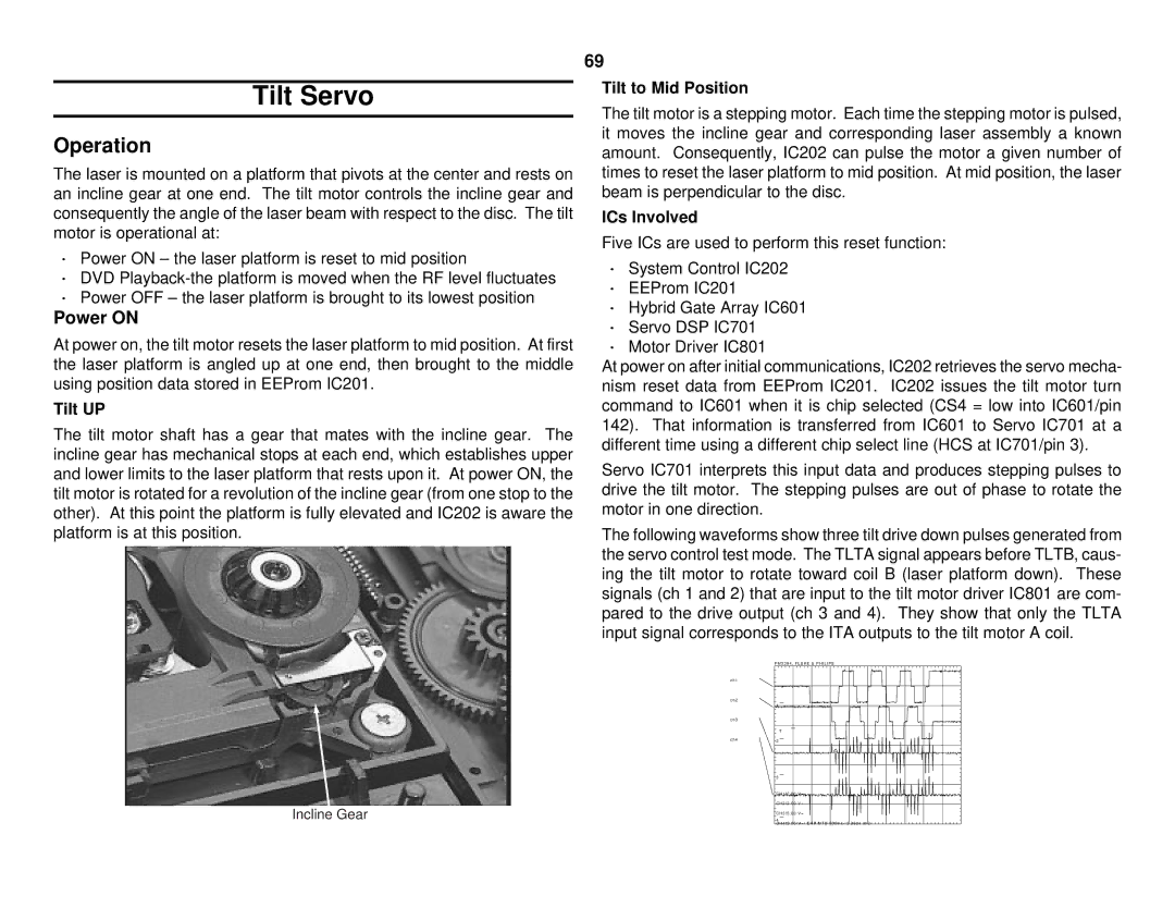
The laser is mounted on a platform that pivots at the center and rests on an incline gear at one end. The tilt motor controls the incline gear and consequently the angle of the laser beam with respect to the disc. The tilt motor is operational at:
·Power ON – the laser platform is reset to mid position
·DVD
·Power OFF – the laser platform is brought to its lowest position
Power ON
At power on, the tilt motor resets the laser platform to mid position. At first the laser platform is angled up at one end, then brought to the middle using position data stored in EEProm IC201.
Tilt UP
The tilt motor shaft has a gear that mates with the incline gear. The incline gear has mechanical stops at each end, which establishes upper and lower limits to the laser platform that rests upon it. At power ON, the tilt motor is rotated for a revolution of the incline gear (from one stop to the other). At this point the platform is fully elevated and IC202 is aware the platform is at this position.
69
Tilt to Mid Position
The tilt motor is a stepping motor. Each time the stepping motor is pulsed, it moves the incline gear and corresponding laser assembly a known amount. Consequently, IC202 can pulse the motor a given number of times to reset the laser platform to mid position. At mid position, the laser beam is perpendicular to the disc.
ICs Involved
Five ICs are used to perform this reset function:
·System Control IC202
·EEProm IC201
·Hybrid Gate Array IC601
·Servo DSP IC701
·Motor Driver IC801
At power on after initial communications, IC202 retrieves the servo mecha- nism reset data from EEProm IC201. IC202 issues the tilt motor turn command to IC601 when it is chip selected (CS4 = low into IC601/pin 142). That information is transferred from IC601 to Servo IC701 at a different time using a different chip select line (HCS at IC701/pin 3).
Servo IC701 interprets this input data and produces stepping pulses to drive the tilt motor. The stepping pulses are out of phase to rotate the motor in one direction.
The following waveforms show three tilt drive down pulses generated from the servo control test mode. The TLTA signal appears before TLTB, caus- ing the tilt motor to rotate toward coil B (laser platform down). These signals (ch 1 and 2) that are input to the tilt motor driver IC801 are com- pared to the drive output (ch 3 and 4). They show that only the TLTA input signal corresponds to the ITA outputs to the tilt motor A coil.
Incline Gear
P M 3 3 9 4 , F L U K E & P H I L I P S
ch1
ch2
1
ch3
T
ch42
3
CH1!2 . 00 V=
CH2!2 . 00 V=
CH3!5 . 00 V=
4
CH4!5 . 00 V= CHP MTB 500ms - 3 . 28dv ch2 -