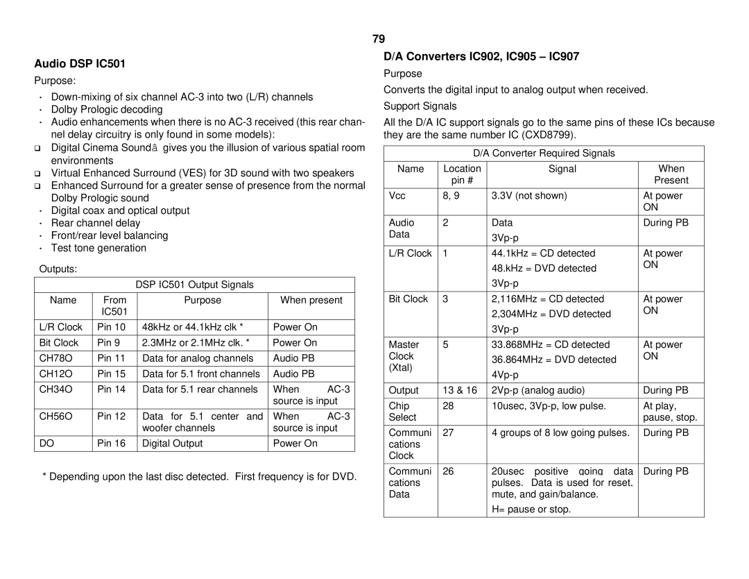
Audio DSP IC501
Purpose:
·
·Dolby Prologic decoding
·Audio enhancements when there is no
qDigital Cinema Soundâ gives you the illusion of various spatial room environments
qVirtual Enhanced Surround (VES) for 3D sound with two speakers
qEnhanced Surround for a greater sense of presence from the normal Dolby Prologic sound
·Digital coax and optical output
·Rear channel delay
·Front/rear level balancing
·Test tone generation
Outputs:
DSP IC501 Output Signals
Name | From | Purpose | When present | |
| IC501 |
|
|
|
|
|
|
|
|
L/R Clock | Pin 10 | 48kHz or 44.1kHz clk * | Power On |
|
|
|
|
|
|
Bit Clock | Pin 9 | 2.3MHz or 2.1MHz clk. * | Power On |
|
|
|
|
|
|
CH78O | Pin 11 | Data for analog channels | Audio PB |
|
|
|
|
|
|
CH12O | Pin 15 | Data for 5.1 front channels | Audio PB |
|
|
|
|
|
|
CH34O | Pin 14 | Data for 5.1 rear channels | When | |
|
|
| source is input | |
|
|
|
|
|
CH56O | Pin 12 | Data for 5.1 center and | When | |
|
| woofer channels | source is input | |
|
|
|
|
|
DO | Pin 16 | Digital Output | Power On |
|
|
|
|
|
|
* Depending upon the last disc detected. First frequency is for DVD.
79
D/A Converters IC902, IC905 – IC907
Purpose
Converts the digital input to analog output when received.
Support Signals
All the D/A IC support signals go to the same pins of these ICs because they are the same number IC (CXD8799).
D/A Converter Required Signals
Name | Location |
| Signal | When |
| pin # |
|
| Present |
|
|
|
| |
Vcc | 8, 9 | 3.3V (not shown) | At power | |
|
|
|
| ON |
|
|
|
|
|
Audio | 2 | Data |
| During PB |
Data |
|
|
| |
|
|
|
| |
|
|
|
| |
L/R Clock | 1 | 44.1kHz = CD detected | At power | |
|
| 48.kHz = DVD detected | ON | |
|
|
| ||
|
|
|
| |
|
|
|
| |
Bit Clock | 3 | 2,116MHz = CD detected | At power | |
|
| 2,304MHz = DVD detected | ON | |
|
|
| ||
|
|
|
| |
|
|
|
| |
Master | 5 | 33.868MHz = CD detected | At power | |
Clock |
| 36.864MHz = DVD detected | ON | |
(Xtal) |
|
| ||
|
|
| ||
|
|
|
| |
|
|
|
| |
Output | 13 & 16 | During PB | ||
|
|
|
| |
Chip | 28 | 10usec, | At play, | |
Select |
|
|
| pause, stop. |
|
|
|
| |
Communi | 27 | 4 groups of 8 low going pulses. | During PB | |
cations |
|
|
|
|
Clock |
|
|
|
|
|
|
|
|
|
Communi | 26 | 20usec | positive going data | During PB |
cations |
| pulses. | Data is used for reset, |
|
Data |
| mute, and gain/balance. |
| |
|
| H= pause or stop. |
| |
|
|
|
|
|