P M 3 3 9 4 , F L U K E & P H I L I P S
ch1
T
1
ch2
ch3
2
ch4
3
CH1!5 . 00 V=
4
CH2!2 . 00 V=
CH3!5 . 00 V=
CH4!5 . 00 V= CHP MTB 200ms - 0 . 40dv ch1+
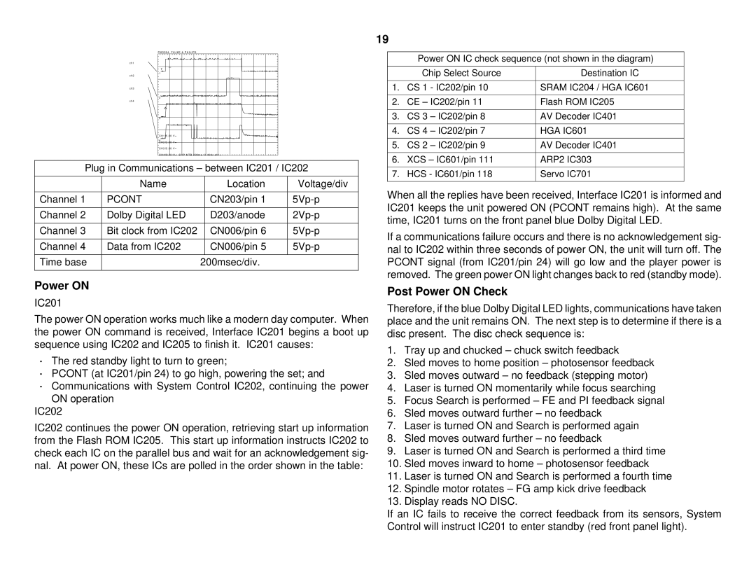
Plug in Communications – between IC201 / IC202
| Name |
| Location | Voltage/div |
|
|
|
|
|
Channel 1 | PCONT |
| CN203/pin 1 | |
|
|
|
|
|
Channel 2 | Dolby Digital LED |
| D203/anode | |
|
|
|
|
|
Channel 3 | Bit clock from IC202 |
| CN006/pin 6 | |
|
|
|
|
|
Channel 4 | Data from IC202 |
| CN006/pin 5 | |
|
|
|
|
|
Time base |
| 200msec/div. |
| |
|
|
|
|
|
Power ON
IC201
The power ON operation works much like a modern day computer. When the power ON command is received, Interface IC201 begins a boot up sequence using IC202 and IC205 to finish it. IC201 causes:
·The red standby light to turn to green;
·PCONT (at IC201/pin 24) to go high, powering the set; and
·Communications with System Control IC202, continuing the power ON operation
IC202
IC202 continues the power ON operation, retrieving start up information from the Flash ROM IC205. This start up information instructs IC202 to check each IC on the parallel bus and wait for an acknowledgement sig- nal. At power ON, these ICs are polled in the order shown in the table:
19
Power ON IC check sequence (not shown in the diagram)
| Chip Select Source | Destination IC |
|
|
|
1. | CS 1 - IC202/pin 10 | SRAM IC204 / HGA IC601 |
|
|
|
2. | CE – IC202/pin 11 | Flash ROM IC205 |
|
|
|
3. | CS 3 – IC202/pin 8 | AV Decoder IC401 |
|
|
|
4. | CS 4 – IC202/pin 7 | HGA IC601 |
|
|
|
5. | CS 2 – IC202/pin 9 | AV Decoder IC401 |
|
|
|
6. | XCS – IC601/pin 111 | ARP2 IC303 |
|
|
|
7. | HCS - IC601/pin 118 | Servo IC701 |
|
|
|
When all the replies have been received, Interface IC201 is informed and IC201 keeps the unit powered ON (PCONT remains high). At the same time, IC201 turns on the front panel blue Dolby Digital LED.
If a communications failure occurs and there is no acknowledgement sig- nal to IC202 within three seconds of power ON, the unit will turn off. The PCONT signal (from IC201/pin 24) will go low and the player power is removed. The green power ON light changes back to red (standby mode).
Post Power ON Check
Therefore, if the blue Dolby Digital LED lights, communications have taken place and the unit remains ON. The next step is to determine if there is a disc present. The disc check sequence is:
1.Tray up and chucked – chuck switch feedback
2.Sled moves to home position – photosensor feedback
3.Sled moves outward – no feedback (stepping motor)
4.Laser is turned ON momentarily while focus searching
5.Focus Search is performed – FE and PI feedback signal
6.Sled moves outward further – no feedback
7.Laser is turned ON and Search is performed again
8.Sled moves outward further – no feedback
9.Laser is turned ON and Search is performed a third time
10.Sled moves inward to home – photosensor feedback
11.Laser is turned ON and Search is performed a fourth time
12.Spindle motor rotates – FG amp kick drive feedback
13.Display reads NO DISC.
If an IC fails to receive the correct feedback from its sensors, System Control will instruct IC201 to enter standby (red front panel light).
