Photo Detectors
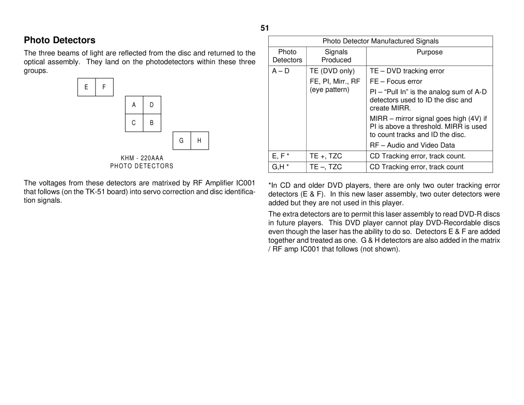
The three beams of light are reflected from the disc and returned to the optical assembly. They land on the photodetectors within these three groups.
E | F |
|
|
AD
C B
G | H |
|
|
KHM - 220AAA
PHOTO DETECTORS
The voltages from these detectors are matrixed by RF Amplifier IC001 that follows (on the
51
Photo Detector Manufactured Signals
Photo | Signals | Purpose |
Detectors | Produced |
|
|
|
|
A – D | TE (DVD only) | TE – DVD tracking error |
| FE, PI, Mirr., RF | FE – Focus error |
| (eye pattern) | PI – “Pull In” is the analog sum of |
|
| |
|
| detectors used to ID the disc and |
|
| create MIRR. |
|
| MIRR – mirror signal goes high (4V) if |
|
| PI is above a threshold. MIRR is used |
|
| to count tracks and ID the disc. |
|
| RF – Audio and Video Data |
|
|
|
E, F * | TE +, TZC | CD Tracking error, track count. |
|
|
|
G,H * | TE | CD Tracking error, track count |
|
|
|
*In CD and older DVD players, there are only two outer tracking error detectors (E & F). In this new laser assembly, two outer detectors were added but they are not used in this player.
The extra detectors are to permit this laser assembly to read