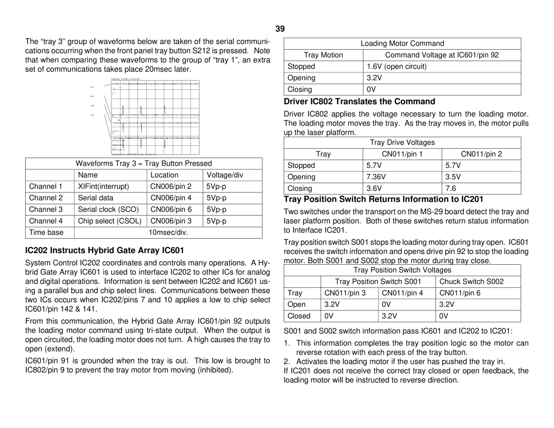
The “tray 3” group of waveforms below are taken of the serial communi- cations occurring when the front panel tray button S212 is pressed. Note that when comparing these waveforms to the group of “tray 1”, an extra set of communications takes place 20msec later.
P M 3 3 9 4 , F L U K E & P H I L I P S
39
| Loading Motor Command |
Tray Motion | Command Voltage at IC601/pin 92 |
|
|
Stopped | 1.6V (open circuit) |
|
|
Opening | 3.2V |
ch1
ch2
ch3
ch4
T
1
2
= A G 3
CH1!5 . 00 V=
CH2!5 . 00 V=
4
CH3!5 . 00 V=
CH4!5 . 00 V= CHP MTB10 . 0ms - 0 . 72dv ch1 -
Closing | 0V |
Driver IC802 Translates the Command
Driver IC802 applies the voltage necessary to turn the loading motor. The loading motor moves the tray. As the tray moves in, the motor pulls up the laser platform.
Tray Drive Voltages
Tray | CN011/pin 1 | CN011/pin 2 |
Waveforms Tray 3 = Tray Button Pressed
| Name | Location | Voltage/div |
|
|
|
|
Channel 1 | XIFint(interrupt) | CN006/pin 2 | |
|
|
|
|
Channel 2 | Serial data | CN006/pin 4 | |
|
|
|
|
Channel 3 | Serial clock (SCO) | CN006/pin 6 | |
|
|
|
|
Channel 4 | Chip select (CSOL) | CN006/pin 3 | |
|
|
|
|
Time base |
| 10msec/div. |
|
|
|
|
|
IC202 Instructs Hybrid Gate Array IC601
System Control IC202 coordinates and controls many operations. A Hy- brid Gate Array IC601 is used to interface IC202 to other ICs for analog and digital operations. Information is sent between IC202 and IC601 us- ing a parallel bus and chip select lines. Communications between these two ICs occurs when IC202/pins 7 and 10 applies a low to chip select IC601/pin 142 & 141.
From this communication, the Hybrid Gate Array IC601/pin 92 outputs the loading motor command using
IC601/pin 91 is grounded when the tray is out. This low is brought to IC802/pin 9 to prevent the tray motor from moving (inhibited).
Stopped | 5.7V | 5.7V |
Opening | 7.36V | 3.5V |
|
|
|
Closing | 3.6V | 7.6 |
Tray Position Switch Returns Information to IC201
Two switches under the transport on the
Tray position switch S001 stops the loading motor during tray open. IC601 receives the switch information and opens drive pin 92 to stop the loading motor. Both S001 and S002 stop the motor during tray close.
Tray Position Switch Voltages
| Tray Position Switch S001 | Chuck Switch S002 | |
|
|
|
|
Tray | CN011/pin 3 | CN011/pin 4 | CN011/pin 6 |
|
|
|
|
Open | 3.2V | 0V | 3.2V |
|
|
|
|
Closed | 0V | 3.2V | 0V |
|
|
|
|
S001 and S002 switch information pass IC601 and IC202 to IC201:
1.This information completes the tray position logic so the motor can reverse rotation with each press of the tray button.
2.Activates the loading motor if the user has pushed the tray in.
If IC201 does not receive the correct tray closed or open feedback, the loading motor will be instructed to reverse direction.