Focus Drive
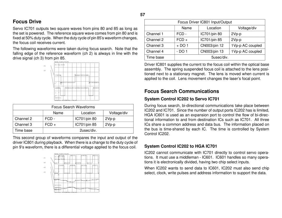
Servo IC701 outputs two square waves from pins 80 and 85 as long as the set is powered. The reference square wave comes from pin 80 and is fixed at 50% duty cycle. When the duty cycle of pin 85’s waveform changes, the focus coil receives current.
The following waveforms were taken during focus search. Note that the falling edge of the reference waveform (ch 2) is always in line with the drive signal (ch 3) from pin 85.
P M 3 3 9 4 , F L U K E & P H I L I P S
ch2: freq= 79 . 4kHz
ch2
ch3
2
T
3
CH2!2 . 00 V=
CH3!2 . 00 V= ALT MTB2 . 00us - 1 . 16dv ch3 -
Focus Search Waveforms
| Name | Location | Voltage/div |
|
|
|
|
Channel 2 | FCD - | IC701/pin 80 | |
|
|
|
|
Channel 3 | FCD + | IC701/pin 85 | |
|
|
|
|
Time base |
| 2usec/div. |
|
|
|
|
|
This second group of waveforms compares the input and output of the driver IC801 during playback. When there is a change to the duty cycle of pin 9’s waveform, there is a differential voltage applied to the focus coil.
P M 3 3 9 4 , F L U K E & P H I L I P S
ch1: pkpk= 3 . 80 V
ch1
ch1: freq= 79 . 4kHz
ch2
1
ch3
ch4T
2
3
CH1!2 . 00 V=
CH2!2 . 00 V=
4
CH3!1 . 00 V~
CH4!1 . 00 V~ ALT MTB5 . 00us - 0 . 94dv ch2+
57
Focus Driver IC801 Input/Output
| Name | Location | Voltage/div |
|
|
|
|
Channel 1 | FCD - | IC701/pin 80 | |
|
|
|
|
Channel 2 | FCD + | IC701/pin 85 | |
|
|
|
|
Channel 3 | + DO 1 | CN003/pin 12 | |
|
|
|
|
Channel 4 | - DO 1 | CN003/pin 13 | |
|
|
|
|
Time base |
| 5usec/div. |
|
|
|
|
|
Driver IC801 supplies the current to the focus coil within the optical base assembly. The spring suspended focus coil is attached to the lens posi- tioned next to a stationary magnet. The lens is moved when current is applied to the coil. Lens movement changes the laser’s focal point.
Focus Search Communications
System Control IC202 to Servo IC701
During focus search,
System Control IC202 to HGA IC701
IC202 cannot communicate with IC701 directly to control servo opera- tions. It must use a middleman - IC601. IC601 handles so many opera- tions it is electronically divided, having two chip select inputs.
When IC202 wants to send data to IC601, IC202 must also send chip select, clock, write pulses and address information to support the data.
