No Power Tray Removal – From the Top
1.Remove the two screws and the mechanism’s top cover to expose the tray and laser platform.
2.Locate the top pawl under the tray by inserting a small screwdriver between the platform and tray. The pawl is just in front of the spindle motor.
3.Slide the pawl to the right to lower the platform and free the tray.
4.Remove the tray.
Tilt Motor
Purpose
Maximum RF output level occurs when the laser beam is perpendicular to the disc’s information layer. The tilt motor raises one end of the laser platform so its beam is perpendicular to the disc.
Access and Operation
The tilt motor is a stepping motor located next to the incline gear. At power OFF, the incline gear lowers one end of the laser platform. At power ON, the incline gear raises the platform to full height.
Incline Gear
The stepping motor then increments the incline gear to the middle posi- tion. This position is stored in EEProm IC201 and updated during the test mode automatic adjustments. During DVD playback, if the RF level fluc- tuates, the tilt motor rotates until the RF level stabilizes. The incline gear remains at the middle position during CD playback.
Sled Position
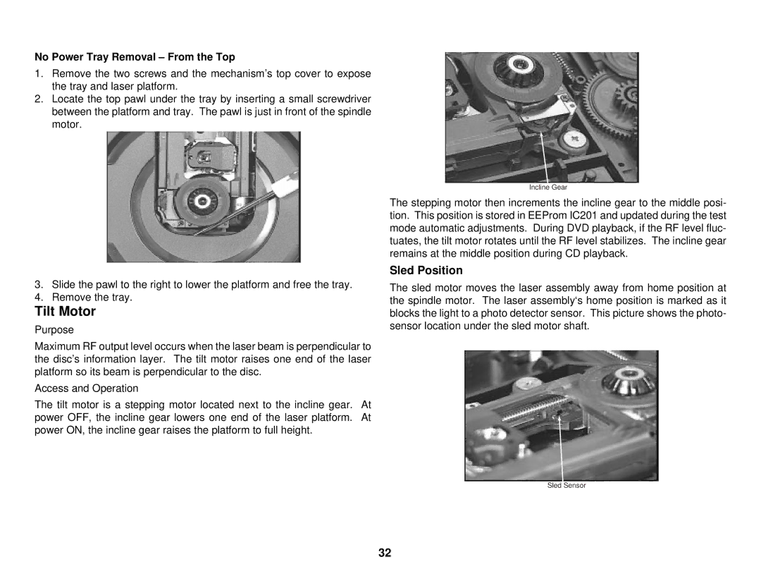
The sled motor moves the laser assembly away from home position at the spindle motor. The laser assembly‘s home position is marked as it blocks the light to a photo detector sensor. This picture shows the photo- sensor location under the sled motor shaft.
Sled Sensor
32
