Sled Stepping Motor
| Name | Location | Voltage/div |
|
|
|
|
Channel 1 | STVC (ref) | IC701/pin 7 | |
|
|
|
|
Channel 2 | SLDA (inward) | IC701/pin 9 | |
|
|
|
|
Channel 3 | SLDB (outward) | IC701/pin 8 | |
|
|
|
|
Time base |
| 5usec/div. |
|
|
|
|
|
The sled motor can be driven manually in either direction to produce the waveforms shown by using the test mode’s manual servo control.
Sled Driver IC802 Sends Voltages to the Stepper Sled Motor
When the input pulses to pulse Sled motor Driver IC802 are not identical to the input reference, the sled motor is driven. At the output, if pulses to the B coil of the stepper type sled motor are lower than the pulses applied to the A coil, the sled moves the laser outward. This can be seen in the waveforms taken at IC802’s output.
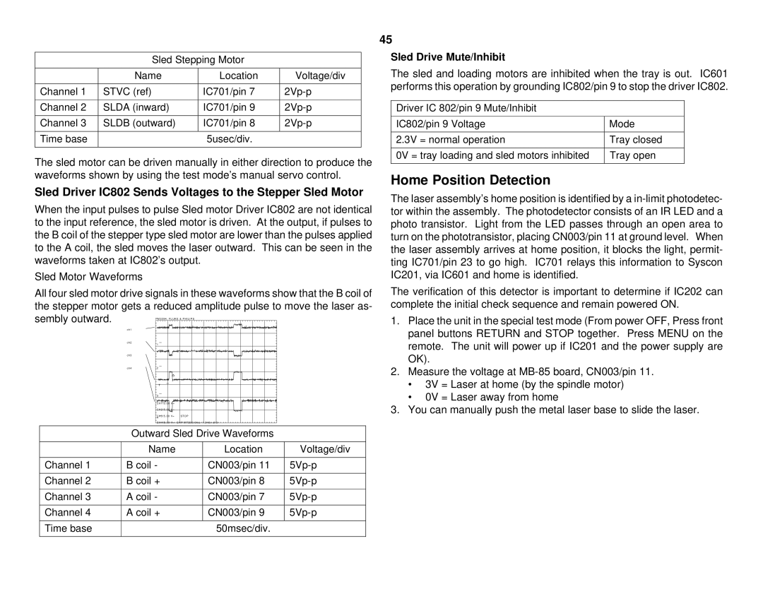
Sled Motor Waveforms
All four sled motor drive signals in these waveforms show that the B coil of the stepper motor gets a reduced amplitude pulse to move the laser as- sembly outward.
ch1
ch2
ch3
ch4
STOP
CHP MTB50 . 0ms - 1 . 34dv ch3 -
Outward Sled Drive Waveforms
| Name | Location | Voltage/div |
|
|
|
|
Channel 1 | B coil - | CN003/pin 11 | |
|
|
|
|
Channel 2 | B coil + | CN003/pin 8 | |
|
|
|
|
Channel 3 | A coil - | CN003/pin 7 | |
|
|
|
|
Channel 4 | A coil + | CN003/pin 9 | |
|
|
|
|
Time base |
| 50msec/div. |
|
|
|
|
|
45
Sled Drive Mute/Inhibit
The sled and loading motors are inhibited when the tray is out. IC601 performs this operation by grounding IC802/pin 9 to stop the driver IC802.
Driver IC 802/pin 9 Mute/Inhibit
IC802/pin 9 Voltage | Mode |
|
|
2.3V = normal operation | Tray closed |
|
|
0V = tray loading and sled motors inhibited | Tray open |
|
|
Home Position Detection
The laser assembly’s home position is identified by a
The verification of this detector is important to determine if IC202 can complete the initial check sequence and remain powered ON.
1.Place the unit in the special test mode (From power OFF, Press front panel buttons RETURN and STOP together. Press MENU on the remote. The unit will power up if IC201 and the power supply are OK).
2.Measure the voltage at
·3V = Laser at home (by the spindle motor)
·0V = Laser away from home
3.You can manually push the metal laser base to slide the laser.