Laser Servo
After the disc tray is closed (disc chucked/platform up), the laser is turned on. The laser on command takes this
1. | System control IC202 | 2. | HGA IC601 |
3. | Servo DSP IC701 | 4. | DVD/CD RF Amplifier IC00 |
5. | Q101 | 6. | DVD/CD Laser Module |
System Control IC202 and HGA IC601 Communications
After System Control receives the platform up verification (S002 in the Tray Motor Drive diagram), it gives the command to move the sled to the home position, then outward. The laser is timed by IC202 to turn on about the time the sled has already moved away from home position and is resting under the disc.
HGA IC601 to Servo DSP IC701 Communications
The laser turn on instruction is sent from IC601 to DSP IC701 using the parallel bus. Since the bus is used by other ICs as well, communication is valid between these ICs when the CS chip select at IC701/pin 3 is low.
Servo DSP IC701 to RF Amplifier IC001 Communications
The laser turn on command uses three of the four communications lines that interconnect IC701 and IC001:
IC701 – IC001 Communications
| Label | Location | Description |
|
|
|
|
1. | SSCS | CN002/pin 5 | High for 16 bits of data (load) |
|
|
|
|
2. | SSRD | CN002/pin 6 | Not used |
|
|
|
|
3. | SSWD | CN002/pin 7 | Clock |
|
|
|
|
4. | SSCK | CN002/pin 8 | Data |
|
|
|
|
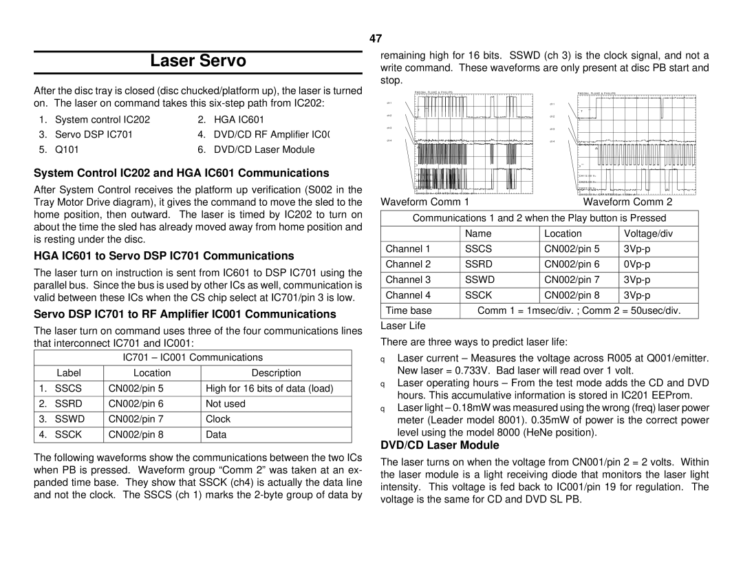
The following waveforms show the communications between the two ICs when PB is pressed. Waveform group “Comm 2” was taken at an ex- panded time base. They show that SSCK (ch4) is actually the data line and not the clock. The SSCS (ch 1) marks the
47
remaining high for 16 bits. SSWD (ch 3) is the clock signal, and not a write command. These waveforms are only present at disc PB start and stop.
P M 3 3 9 4 , F L U K E & P H I L I P S | P M 3 3 9 4 , F L U K E & P H I L I P S |
| |
ch1 |
| ch1 |
|
|
|
| |
T |
| T |
|
|
|
| |
ch2 |
| ch2 |
|
1 |
| 1 |
|
ch3 |
| ch3 |
|
ch4 |
| ch4 |
|
2 |
|
| |
|
| 2 |
|
3 |
| 3 |
|
CH1!2 . 00 V= |
| CH1!2 . 00 V= |
|
|
|
| |
CH2!5 . 00 V= |
| CH2!5 . 00 V= |
|
CH3!2 . 00 V= |
| CH3!2 . 00 V= |
|
4 |
| 4 |
|
CH4!2 . 00 V= | CHP MTB1 . 00ms - 0 . 30dv ch1+ | CH4!2 . 00 V= CHP MTB50 . 0us - 1 . 58dv ch1+ | |
Waveform Comm 1 | Waveform Comm 2 | ||
Communications 1 and 2 when the Play button is Pressed | |||
| Name | Location | Voltage/div |
Channel 1 | SSCS | CN002/pin 5 | |
Channel 2 | SSRD | CN002/pin 6 | |
Channel 3 | SSWD | CN002/pin 7 | |
Channel 4 | SSCK | CN002/pin 8 | |
Time base | Comm 1 = 1msec/div. ; Comm 2 = 50usec/div. | ||
Laser Life
There are three ways to predict laser life:
qLaser current – Measures the voltage across R005 at Q001/emitter. New laser = 0.733V. Bad laser will read over 1 volt.
qLaser operating hours – From the test mode adds the CD and DVD hours. This accumulative information is stored in IC201 EEProm.
qLaser light – 0.18mW was measured using the wrong (freq) laser power meter (Leader model 8001). 0.35mW of power is the correct power level using the model 8000 (HeNe position).
DVD/CD Laser Module
The laser turns on when the voltage from CN001/pin 2 = 2 volts. Within the laser module is a light receiving diode that monitors the laser light intensity. This voltage is fed back to IC001/pin 19 for regulation. The voltage is the same for CD and DVD SL PB.