EVS Toolroom Lathes | O P E R A T I O N | For Machines Mfg. Since 7/09 |
|
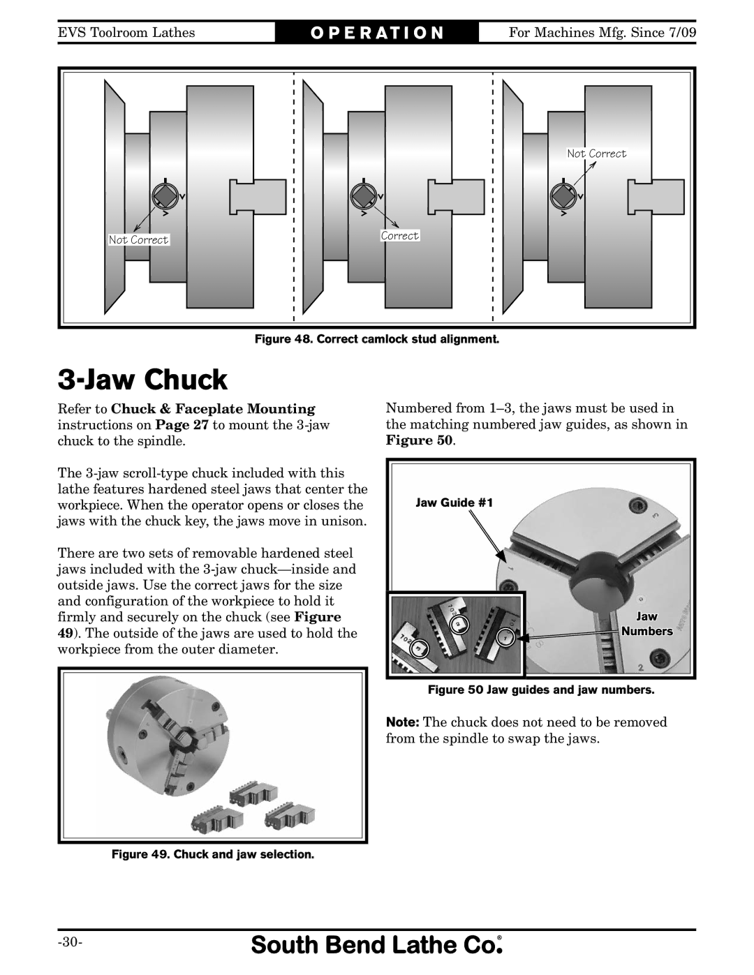
| Not Correct |
Not Correct | Correct |
|
|
|
Figure 48. Correct camlock stud alignment.
3-Jaw Chuck
Refer to Chuck & Faceplate Mounting instructions on Page 27 to mount the
The
There are two sets of removable hardened steel jaws included with the
49). The outside of the jaws are used to hold the workpiece from the outer diameter.
Numbered from
Jaw Guide #1 |
Jaw |
Numbers |
Figure 50 Jaw guides and jaw numbers.
Note: The chuck does not need to be removed from the spindle to swap the jaws.