EVS Toolroom Lathes | M A I N T E N A N C E | For Machines Mfg. Since 7/09 |
Cutting Fluid System
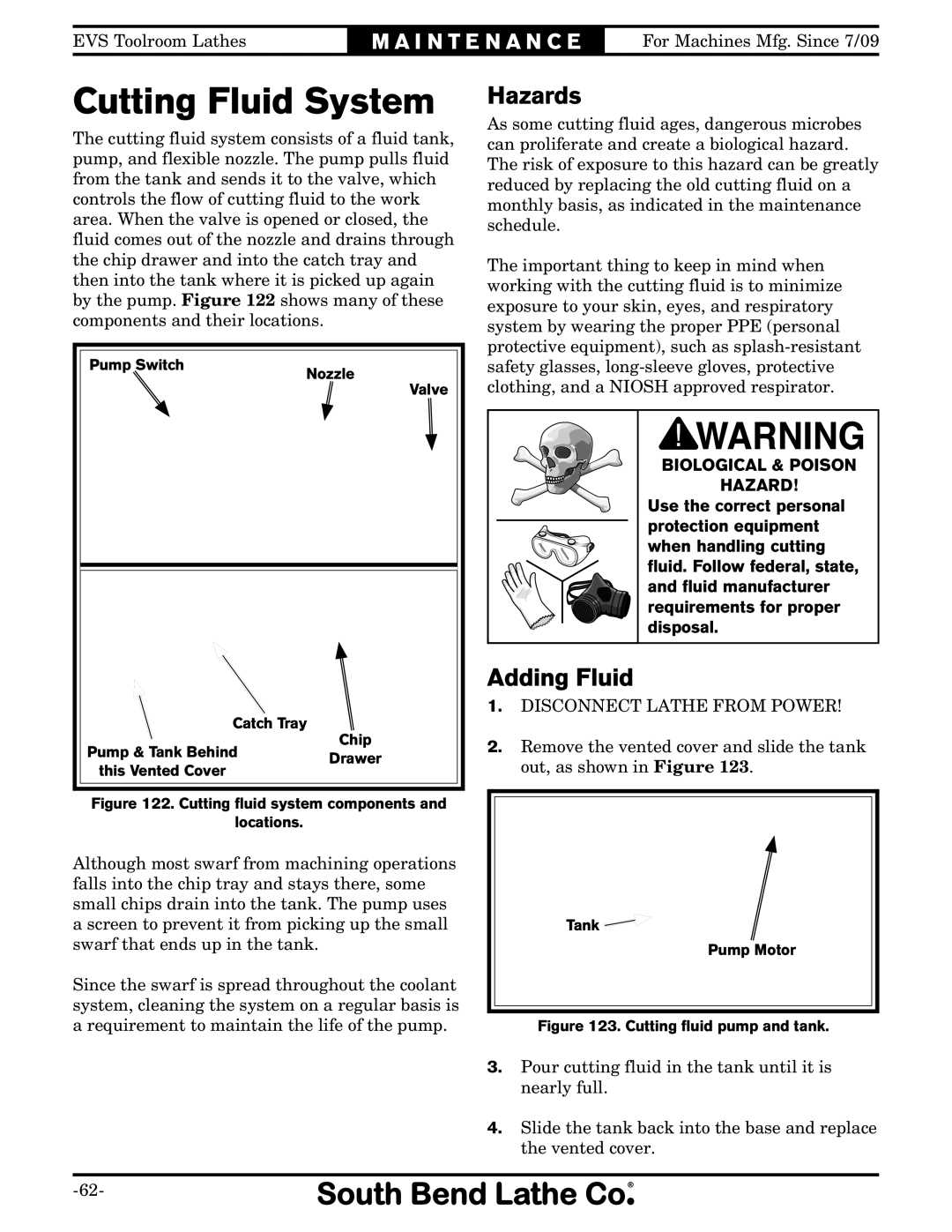
The cutting fluid system consists of a fluid tank, pump, and flexible nozzle. The pump pulls fluid from the tank and sends it to the valve, which controls the flow of cutting fluid to the work area. When the valve is opened or closed, the fluid comes out of the nozzle and drains through the chip drawer and into the catch tray and then into the tank where it is picked up again by the pump. Figure 122 shows many of these components and their locations.
Pump Switch | Nozzle | ||
| |||
|
| Valve | |
| Catch Tray | Chip | |
Pump & Tank Behind | |||
Drawer | |||
this Vented Cover |
| ||
|
| ||
Figure 122. Cutting fluid system components and
locations.
Although most swarf from machining operations falls into the chip tray and stays there, some small chips drain into the tank. The pump uses a screen to prevent it from picking up the small swarf that ends up in the tank.
Since the swarf is spread throughout the coolant system, cleaning the system on a regular basis is a requirement to maintain the life of the pump.
Hazards
As some cutting fluid ages, dangerous microbes can proliferate and create a biological hazard. The risk of exposure to this hazard can be greatly reduced by replacing the old cutting fluid on a monthly basis, as indicated in the maintenance schedule.
The important thing to keep in mind when working with the cutting fluid is to minimize exposure to your skin, eyes, and respiratory system by wearing the proper PPE (personal protective equipment), such as
BIOLOGICAL & POISON |
HAZARD! |
Use the correct personal |
protection equipment |
when handling cutting |
fluid. Follow federal, state, |
and fluid manufacturer |
requirements for proper |
disposal. |
Adding Fluid
1.DISCONNECT LATHE FROM POWER!
2.Remove the vented cover and slide the tank out, as shown in Figure 123.
Tank ![]()
Pump Motor
Figure 123. Cutting fluid pump and tank.
3.Pour cutting fluid in the tank until it is nearly full.
4.Slide the tank back into the base and replace the vented cover.