Setting up the outputs | Analog Outputs |
|
|
Setting up the outputs
Output Amplifiers
This arbitrary waveform generator board uses separate output am- plifiers for each channel. This gives you the possibility to seperately set up the channel outputs to best suit your application
The output amplifiers can easily be set by the corresponding am- plitude registers.
The table below shows the available registers to set up the output amplitude for your type of board.
Register | Value | Direction | Description | Amplitude range |
SPC_AMP0 | 30010 | r/w | Defines the amplitude of channel0. | 100 mV up to 3000 mV |
SPC_AMP1 | 30110 | r/w | Defines the amplitude of channel1. | 100 mV up to 3000 mV |
|
|
|
|
|
SPC_AMP2 | 30210 | r/w | Defines the amplitude of channel2. | 100 mV up to 3000 mV |
|
|
|
|
|
SPC_AMP3 | 30310 | r/w | Defines the amplitude of channel3. | 100 mV up to 3000 mV |
The amplitude can be changed at any time even if the board is running and outputting a signal to the con- nectors. The board will not be stopped when changing these settings.
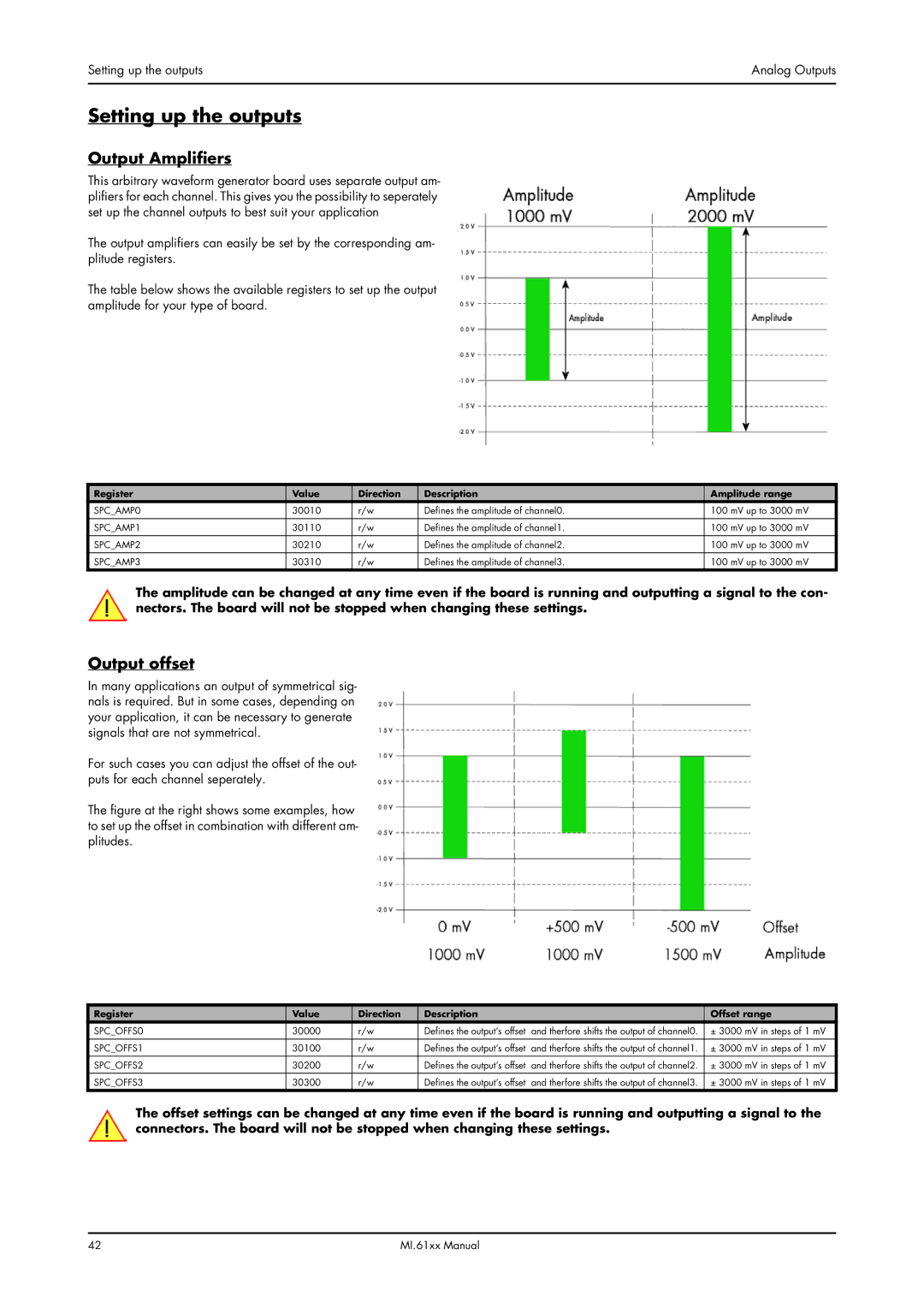
Output offset
In many applications an output of symmetrical sig- nals is required. But in some cases, depending on your application, it can be necessary to generate signals that are not symmetrical.
For such cases you can adjust the offset of the out- puts for each channel seperately.
The figure at the right shows some examples, how to set up the offset in combination with different am- plitudes.
Register | Value | Direction | Description |
| Offset range |
SPC_OFFS0 | 30000 | r/w | Defines the output’s offset | and therfore shifts the output of channel0. | ± 3000 mV in steps of 1 mV |
SPC_OFFS1 | 30100 | r/w | Defines the output’s offset | and therfore shifts the output of channel1. | ± 3000 mV in steps of 1 mV |
|
|
|
|
|
|
SPC_OFFS2 | 30200 | r/w | Defines the output’s offset | and therfore shifts the output of channel2. | ± 3000 mV in steps of 1 mV |
SPC_OFFS3 | 30300 | r/w | Defines the output’s offset | and therfore shifts the output of channel3. | ± 3000 mV in steps of 1 mV |
The offset settings can be changed at any time even if the board is running and outputting a signal to the connectors. The board will not be stopped when changing these settings.
42 | MI.61xx Manual |