Standard generation modes | Programming |
|
|
To prevent the program from this deadlock, a second task must be used which can send the SPC_STOP signal to stop the board. Another possibility, that does not require the need of a second task is to define a timeout value.
Register
SPC_TIMEOUT
Value | Direction | Description |
295130 | r/w | Defines a time in ms after which the function SPC_STARTANDWAIT terminates itself. |
|
|
|
This is the easiest and safest way to use the interrupt driven mode. If the board started in the interrupts mode it definitely will not return until either the recording has finished or the timeout time has expired. In that case the function will return with an error code. See the appendix for details.
The following excerpt of a sample program gives you an example of how to start the board in the interrupt driven mode. It is assumed that all board setup has been done before.
SpcSetParam | (hDrv, | SPC_TIMEOUT, 1000); | // Define the timeout to 1000 ms = 1 | second |
nErr = SpcSetParam | (hDrv, SPC_COMMAND, | SPC_STARTANDWAIT); // Starts the board in the interrupt | driven mode | |
if (nErr == | ERR_TIMEOUT) | // Checks for the timeout |
| |
printf ("No trigger found. Timeout | has expired.\n"); |
| ||
An example on how to get a second task that can do some monitoring on the running task and eventually send the SPC_STOP command can be found on the Spectrum driver CD that has been shipped with your board. The latest examples can also be down loaded via our website at
Data organization
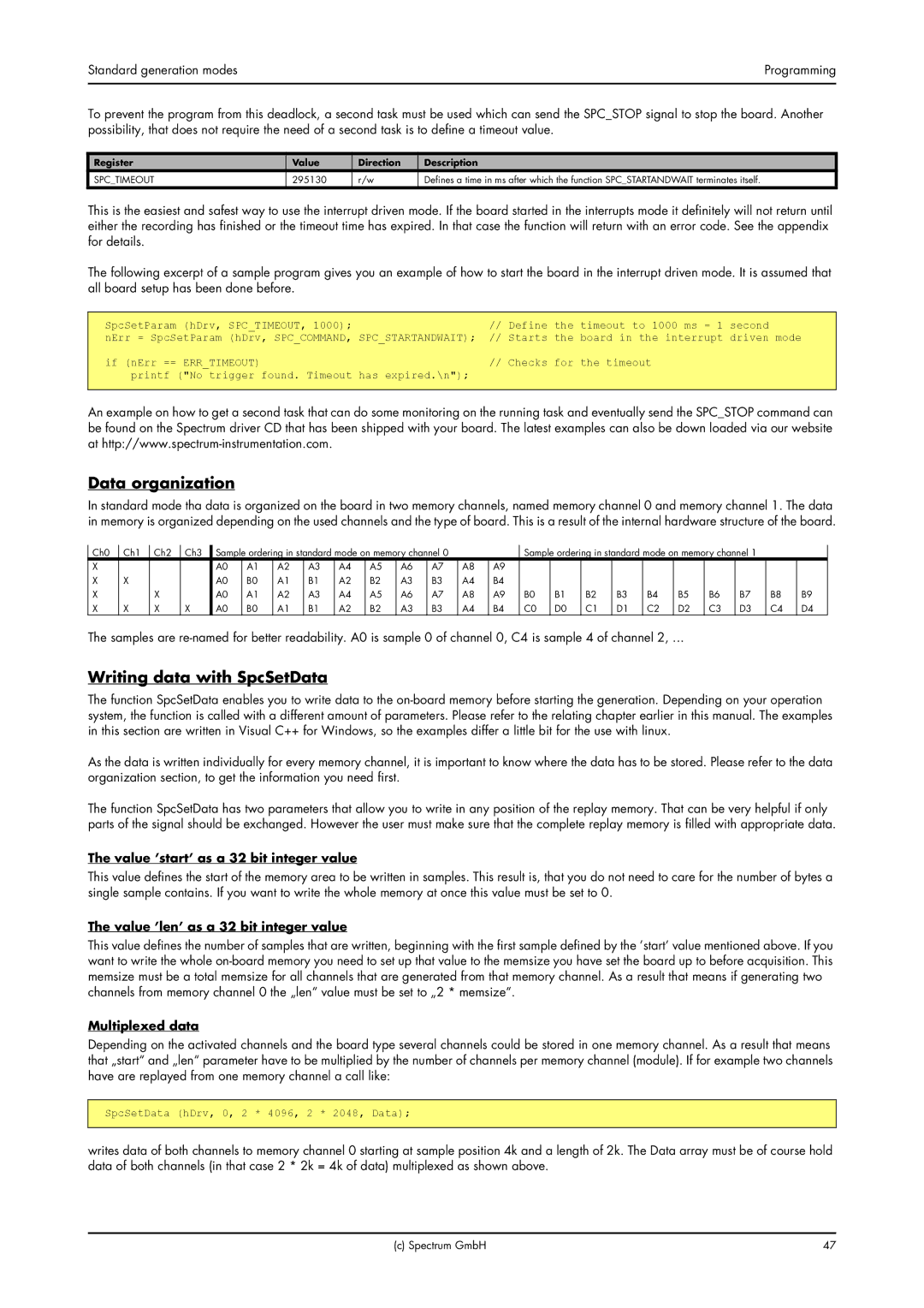
In standard mode tha data is organized on the board in two memory channels, named memory channel 0 and memory channel 1. The data in memory is organized depending on the used channels and the type of board. This is a result of the internal hardware structure of the board.
Ch0 | Ch1 | Ch2 | Ch3 | Sample ordering in standard mode on memory channel 0 |
|
| Sample ordering in standard mode on memory channel 1 |
|
| ||||||||||||||
X |
|
|
| A0 | A1 | A2 | A3 | A4 | A5 | A6 | A7 | A8 | A9 |
|
|
|
|
|
|
|
|
|
|
X | X |
|
| A0 | B0 | A1 | B1 | A2 | B2 | A3 | B3 | A4 | B4 |
|
|
|
|
|
|
|
|
|
|
X |
| X |
| A0 | A1 | A2 | A3 | A4 | A5 | A6 | A7 | A8 | A9 | B0 | B1 | B2 | B3 | B4 | B5 | B6 | B7 | B8 | B9 |
X | X | X | X | A0 | B0 | A1 | B1 | A2 | B2 | A3 | B3 | A4 | B4 | C0 | D0 | C1 | D1 | C2 | D2 | C3 | D3 | C4 | D4 |
The samples are
Writing data with SpcSetData
The function SpcSetData enables you to write data to the
As the data is written individually for every memory channel, it is important to know where the data has to be stored. Please refer to the data organization section, to get the information you need first.
The function SpcSetData has two parameters that allow you to write in any position of the replay memory. That can be very helpful if only parts of the signal should be exchanged. However the user must make sure that the complete replay memory is filled with appropriate data.
The value ’start’ as a 32 bit integer value
This value defines the start of the memory area to be written in samples. This result is, that you do not need to care for the number of bytes a single sample contains. If you want to write the whole memory at once this value must be set to 0.
The value ’len’ as a 32 bit integer value
This value defines the number of samples that are written, beginning with the first sample defined by the ’start’ value mentioned above. If you want to write the whole
Multiplexed data
Depending on the activated channels and the board type several channels could be stored in one memory channel. As a result that means that „start“ and „len“ parameter have to be multiplied by the number of channels per memory channel (module). If for example two channels have are replayed from one memory channel a call like:
SpcSetData (hDrv, 0, 2 * 4096, 2 * 2048, Data);
writes data of both channels to memory channel 0 starting at sample position 4k and a length of 2k. The Data array must be of course hold data of both channels (in that case 2 * 2k = 4k of data) multiplexed as shown above.
(c) Spectrum GmbH | 47 |
