Pin assignment of the internal multipin connector
Pin assignment of the internal multipin connector
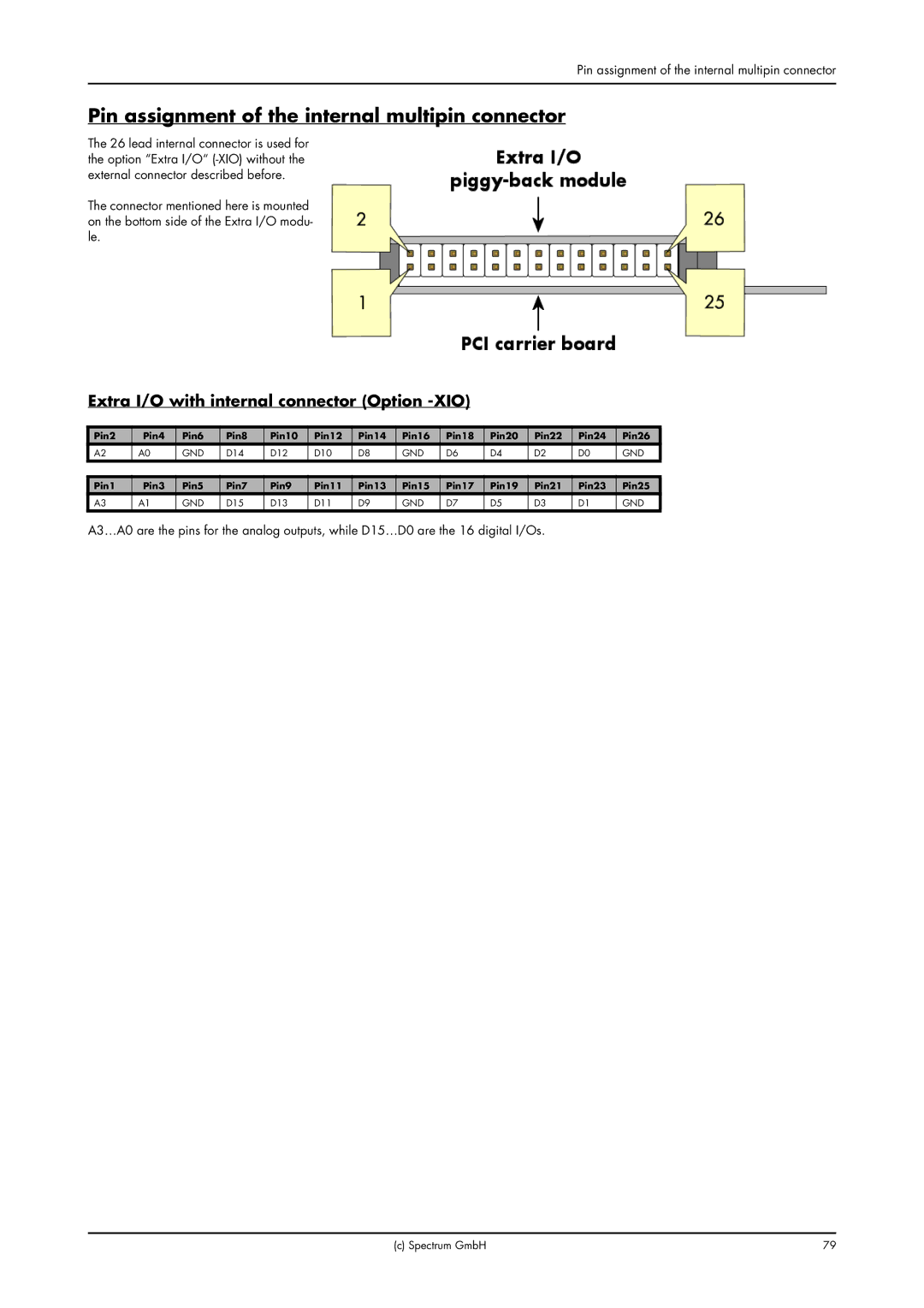
The 26 lead internal connector is used for the option “Extra I/O“
The connector mentioned here is mounted on the bottom side of the Extra I/O modu- le.
Extra I/O with internal connector (Option -XIO)
Pin2 | Pin4 | Pin6 | Pin8 | Pin10 | Pin12 | Pin14 | Pin16 | Pin18 | Pin20 | Pin22 | Pin24 | Pin26 |
A2 | A0 | GND | D14 | D12 | D10 | D8 | GND | D6 | D4 | D2 | D0 | GND |
|
|
|
|
|
|
|
|
|
|
|
|
|
Pin1 | Pin3 | Pin5 | Pin7 | Pin9 | Pin11 | Pin13 | Pin15 | Pin17 | Pin19 | Pin21 | Pin23 | Pin25 |
A3 | A1 | GND | D15 | D13 | D11 | D9 | GND | D7 | D5 | D3 | D1 | GND |
A3…A0 are the pins for the analog outputs, while D15…D0 are the 16 digital I/Os.
(c) Spectrum GmbH | 79 |