Example program | Option Gated Replay |
|
|
Due to the structure of the
Internally a
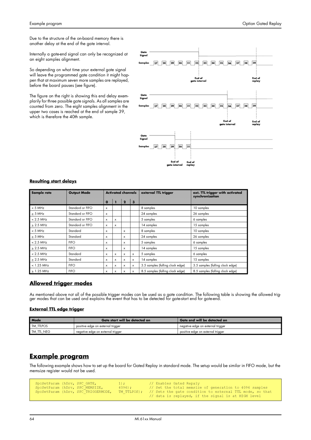
So depending on what time your external gate signal will leave the programmed gate condition it might hap- pen that at maximum seven more samples are replayed, before the board pauses (see figure).
The figure on the right is showing this end delay exem- plarily for three possible gate signals. As all samples are counted from zero. The eight samples alignment in the upper two cases is reached at the end of sample 39, which is therefore the 40th sample.
Resulting start delays
Sample rate | Output Mode | Activated channels | external TTL trigger | ext. TTL trigger with activated | |||
|
|
|
|
|
|
| synchronization |
|
| 0 | 1 | 2 | 3 |
|
|
< 5 MHz | Standard or FIFO | x |
|
|
| 8 samples | 10 samples |
> 5 MHz | Standard or FIFO | x |
|
|
| 24 samples | 26 samples |
< 2.5 MHz | Standard or FIFO | x | x |
|
| 5 samples | 6 samples |
|
|
|
|
|
|
|
|
> 2.5 MHz | Standard or FIFO | x | x |
|
| 14 samples | 15 samples |
< 5 MHz | Standard | x |
| x |
| 8 samples | 10 samples |
> 5 MHz | Standard | x |
| x |
| 24 samples | 26 samples |
|
|
|
|
|
|
|
|
< 2.5 MHz | FIFO | x |
| x |
| 5 samples | 6 samples |
> 2.5 MHz | FIFO | x |
| x |
| 14 samples | 15 samples |
< 2.5 MHz | Standard | x | x | x | x | 5 samples | 6 samples |
|
|
|
|
|
|
|
|
> 2.5 MHz | Standard | x | x | x | x | 14 samples | 15 samples |
< 1.25 MHz | FIFO | x | x | x | x | 3.5 samples (falling clock edge) | 3.5 samples (falling clock edge) |
> 1.25 MHz | FIFO | x | x | x | x | 8.5 samples (falling clock edge) | 8.5 samples (falling clock edge) |
Allowed trigger modes
As mentioned above not all of the possible trigger modes can be used as a gate condition. The following table is showing the allowed trig- ger modes that can be used and explains the event that has to be detected for
External TTL edge trigger
Mode | Gate start will be detected on | Gate end will be detected on |
TM_TTLPOS | positive edge on external trigger | negative edge on external trigger |
|
|
|
TM_TTL_NEG | negative edge on external trigger | positive edge on external trigger |
Example program
The following example shows how to set up the board for Gated Replay in standard mode. The setup would be similar in FIFO mode, but the memsize register would not be used.
SpcSetParam (hDrv, SPC_GATE, | 1); | // Enables Gated | Repaly | generation | to 4096 samples | ||||
SpcSetParam | (hDrv, | SPC_MEMSIZE, | 4096); | // Set the | total | memsize of | |||
SpcSetParam | (hDrv, | SPC_TRIGGERMODE, | TM_TTLPOS); | // | Sets the gate condition to external | TTL mode, so that | |||
|
|
|
| // | data is | replayed, if the | signal is at HIGH level | ||
64 | MI.61xx Manual |