General Description | Trigger modes and appendant registers |
|
|
Trigger modes and appendant registers
General Description
Concerning the trigger modes of the Spectrum MI, MC and MX D/A boards, you can choose between three external TTL trigger modes and one internal software trigger. This chapter is about to explain the different trigger modes and setting up the board’s registers for the desired mode. Every analog Spectrum board has one dedicated SMB connector mounted in it’s bracket for feeding in an external trigger signal or outputting a trigger signal of an internal trigger event. As only one connector is available for external trigger I/O, it is not possible to forward the external trigger signal that is fed in to another board. If this is necessary, you need to first split up the external trigger signal.
Software trigger
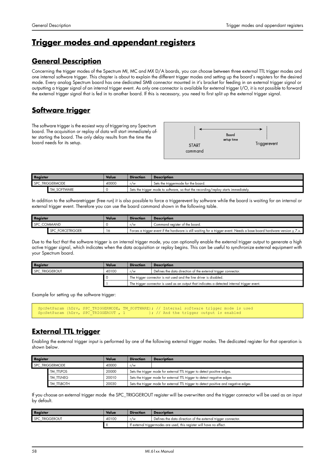
The software trigger is the easiest way of triggering any Spectrum board. The acquisition or replay of data will start immediately af- ter starting the board. The only delay results from the time the board needs for its setup.
Register | Value | Direction | Description | |
SPC_TRIGGERMODE | 40000 | r/w | Sets the triggermode for the board. | |
| TM_SOFTWARE | 0 | Sets the trigger mode to software, so that the recording/replay starts immediately. | |
In addition to the softwaretrigger (free run) it is also possible to force a triggerevent by software while the board is waiting for an internal or external trigger event. Therefore you can use the board command shown in the following table.
Register | Value | Direction | Description | |
SPC_COMMAND | 0 | r/w | Command register of the board. | |
| SPC_FORCETRIGGER | 16 | Forces a trigger event if the hardware is still waiting for a trigger event. Needs a base board hardware version > 7.x. | |
Due to the fact that the software trigger is an internal trigger mode, you can optionally enable the external trigger output to generate a high active trigger signal, which indicates when the data acquisition or replay begins. This can be useful to synchronize external equipment with your Spectrum board.
Register | Value | Direction | Description |
SPC_TRIGGEROUT | 40100 | r/w | Defines the data direction of the external trigger connector. |
| 0 | The trigger connector is not used and the line driver is disabled. | |
| 1 | The trigger connector is used as an output that indicates a detected internal trigger event. | |
Example for setting up the software trigger:
SpcSetParam | (hDrv, | SPC_TRIGGERMODE, | TM_SOFTWARE); | // | Internal software trigger | mode is | used | |
SpcSetParam | (hDrv, | SPC_TRIGGEROUT , | 1 | ); | // | And the trigger output is | enabled |
|
|
|
|
|
|
|
|
|
|
External TTL trigger
Enabling the external trigger input is performed by one of the following external trigger modes. The dedicated register for that operation is shown below.
Register | Value | Direction | Description | |
SPC_TRIGGERMODE | 40000 | r/w |
| |
| TM_TTLPOS | 20000 | Sets the trigger mode for external TTL trigger to detect positive edges. | |
|
|
|
| |
| TM_TTLNEG | 20010 | Sets the trigger mode for external TTL trigger to detect negative edges | |
| TM_TTLBOTH | 20030 | Sets the trigger mode for external TTL trigger to detect positive and negative edges | |
If you choose an external trigger mode the SPC_TRIGGEROUT register will be overwritten and the trigger connector will be used as an input by default.
Register | Value | Direction | Description |
SPC_TRIGGEROUT | 40100 | r/w | Defines the data direction of the external trigger connector. |
| X | If external triggermodes are used, this register will have no effect. | |
58 | MI.61xx Manual |