Analog Outputs | Setting up the outputs |
|
|
Maximum Output Range
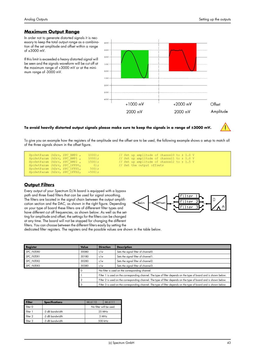
In order not to generate distorted signals it is nec- essary to keep the total output range as a combina- tion of the set amplitude and offset within a range of ±3000 mV.
If this limit is exceeded a heavy distorted signal will be seen and the signals waveform will be cut off at the maximum range of +3000 mV or at the mini- mum range of
To avoid heavily distorted output signals please make sure to keep the signals in a range of ±3000 mV.
To give you an example how the registers of the amplitude and the offset are to be used, the following example shows a setup to match all of the three signals shown in the offset figure.
SpcSetParam (hDrv, SPC_AMP0 , | 1000); | // Set up amplitude of channel0 to ± 1.0 | V |
SpcSetParam (hDrv, SPC_AMP1 , | 1000); | // Set up amplitude of channel1 to ± 1.0 | V |
SpcSetParam (hDrv, SPC_AMP2 , | 1500); | // Set up amplitude of channel2 to ± 1.5 | V |
SpcSetParam (hDrv, SPC_OFFS0, | 0); | // Set the output offsets |
|
SpcSetParam (hDrv, SPC_OFFS1, | 500); |
|
|
SpcSetParam (hDrv, SPC_OFFS2, |
|
|
Output Filters
Every output of your Spectrum D/A board is equipped with a bypass path and three fixed filters that can be used for signal smoothing. The filters are located in the signal chain between the output amplifi- cation section and the DAC, as shown in the right figure. Depending on your type of board these filters are of differerent filter types and have different cut off frequencies, as shown below. As well as the set- ting for amplitude and offset, the settings for the filters can be changed at any time. The board will not be stopped for changing the different filters. You can choose between the different filters easily by setting the
dedicated filter registers. The registers and the possible values are shown in the table below.
Register |
| Value |
| Direction | Description | |||
SPC_FILTER0 |
| 30080 |
| r/w | Sets the signal filter of channel0. | |||
SPC_FILTER1 |
| 30180 |
| r/w | Sets the signal filter of channel1. | |||
|
|
|
|
|
|
|
|
|
SPC_FILTER2 |
| 30280 |
| r/w | Sets the signal filter of channel2. | |||
SPC_FILTER3 |
| 30380 |
| r/w | Sets the signal filter of channel3. | |||
|
| 0 |
|
| No filter is used on the corresponding channel. | |||
|
|
|
|
|
|
|
| |
|
| 1 |
|
| Filter 1 is used on the corresponding channel. The type of filter depends on the type of board and is shown below. | |||
|
| 2 |
|
| Filter 2 is used on the corresponding channel. The type of filter depends on the type of board and is shown below. | |||
|
| 3 |
|
| Filter 3 is used on the corresponding channel. The type of filter depends on the type of board and is shown below. | |||
|
|
|
|
|
|
|
|
|
Filter | Specifications |
| MI.6110 |
| MI.6111 |
|
| |
filter 0 |
|
|
| No filter will be used. |
|
| ||
filter 1 |
|
|
| 25 MHz |
|
| ||
|
|
|
|
|
|
|
| |
filter 2 |
|
|
| 5 MHz |
|
| ||
filter 3 |
|
|
| 500 kHz |
|
| ||
(c) Spectrum GmbH | 43 |