2.Drill a hole in one area of the cut area that will allow the blade of a jig saw to be inserted. Insert and cut out the area on the panel using the jig saw.
3.Next drill the four holes required to insert the chartplotter with the mounting studs.
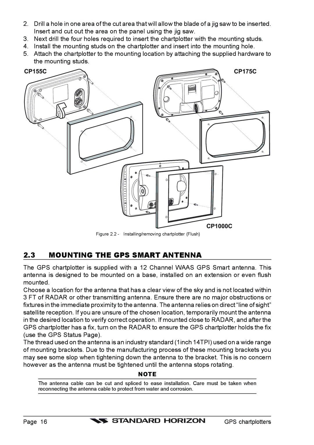
4.Install the mounting studs on the chartplotter and insert into the mounting hole.
5.Attach the chartplotter to the mounting location by attaching the supplied hardware to the mounting studs.
Figure 2.2 - Installing/removing chartplotter (Flush)
2.3MOUNTING THE GPS SMART ANTENNA
The GPS chartplotter is supplied with a 12 Channel WAAS GPS Smart antenna. This antenna is designed to be mounted on a base, installed on an extension or even flush mounted.
Choose a location for the antenna that has a clear view of the sky and is not located within 3 FT of RADAR or other transmitting antenna. Ensure there are no major obstructions or fixtures in the immediate proximity to the antenna. The antenna relies on direct “line of sight” satellite reception. If you are unsure of the chosen location, temporarily mount the antenna in the desired location to verify correct operation. If mounted close to RADAR, and after the GPS chartplotter has a fix, turn on the RADAR to ensure the GPS chartplotter holds the fix (use the GPS Status Page).
The thread used on the antenna is an industry standard (1inch 14TPI) used on a wide range of mounting brackets. Due to the manufacturing process of these mounting brackets you may see some slop when tightening down the antenna to the bracket. This is no concern however as the antenna must be tightened until the antenna stops rotating.
NOTE
The antenna cable can be cut and spliced to ease installation. Care must be taken when reconnecting the antenna cable to protect from water and corrosion.
Page 16 |
| GPS chartplotters |
|