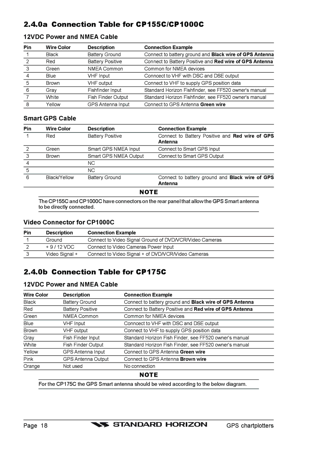
2.4.0a Connection Table for CP155C/CP1000C 12VDC Power and NMEA Cable
Pin | Wire Color | Description | Connection Example |
1 | Black | Battery Ground | Connect to battery ground and Black wire of GPS Antenna |
2 | Red | Battery Positive | Connect to Battery Positive and Red wire of GPS Antenna |
3 | Green | NMEA Common | Common for NMEA devices |
4 | Blue | VHF Input | Conncect to VHF with DSC and DSE output |
5 | Brown | VHF output | Connect to VHF to supply GPS position data |
6 | Gray | Fishfinder Input | Standard Horizon Fishfinder, see FF520 owner's manual |
7 | White | Fish Finder Output | Standard Horizon Fishfinder, see FF520 owner's manual |
8 | Yellow | GPS Antenna Input | Connect to GPS Antenna Green wire |
Smart GPS Cable
Pin | Wire Color | Description | Connection Example |
1 | Red | Battery Positive | Connect to Battery Positive and Red wire of GPS |
|
|
| Antenna |
2 | Green | Smart GPS NMEA Input | Connect to Smart GPS Input |
3 | Brown | Smart GPS NMEA Output | Connect to Smart GPS Output |
4 |
| NC |
|
5 |
| NC |
|
6 | Black/Yellow | Battery Ground | Connect to battery ground and Black wire of GPS |
|
|
| Antenna |
NOTE
The CP155C and CP1000C have connectors on the rear panel that allow the GPS Smart antenna to be directly connected.
Video Connector for CP1000C
Pin | Description | Connection Example |
1 | Ground | Connect to Video Signal Ground of DVD/VCR/Video Cameras |
2 | + 9 / 12 VDC | Connect to Video Cameras Power Input |
3 | Video Signal + | Connect to Video Signal + of DVD/VCR/Video Cameras |
2.4.0b Connection Table for CP175C 12VDC Power and NMEA Cable
Wire Color | Description | Connection Example |
Black | Battery Ground | Connect to battery ground and Black wire of GPS Antenna |
Red | Battery Positive | Connect to Battery Positive and Red wire of GPS Antenna |
Green | NMEA Common | Common for NMEA devices |
Blue | VHF Input | Conncect to VHF with DSC and DSE output |
Brown | VHF output | Connect to VHF to supply GPS position data |
Gray | Fish Finder Input | Standard Horizon Fish Finder, see FF520 owner's manual |
White | Fish Finder Output | Standard Horizon Fish Finder, see FF520 owner's manual |
Yellow | GPS Antenna Input | Connect to GPS Antenna Green wire |
Pink | GPS Antenna Output | Connect to GPS Antenna Brown wire |
Orange | Not used | No connection |
|
| NOTE |
For the CP175C the GPS Smart antenna should be wired according to the below diagram.
Page 18 |
| GPS chartplotters |
|
