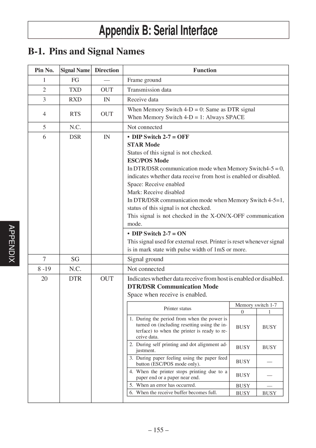
Appendix B: Serial Interface
B-1. Pins and Signal Names
|
| Pin No. | Signal Name | Direction |
|
| Function |
|
|
|
|
|
|
|
|
|
|
|
|
| |
|
| 1 | FG | — | Frame ground |
|
|
| ||
|
|
|
|
|
|
|
|
|
| |
|
| 2 | TXD | OUT |
| Transmission data |
|
|
| |
|
|
|
|
|
|
|
|
|
| |
|
| 3 | RXD | IN |
| Receive data |
|
|
| |
|
|
|
|
|
|
|
|
|
| |
|
| 4 | RTS | OUT |
| When Memory Switch |
|
| ||
|
|
| When Memory Switch |
|
| |||||
|
|
|
|
|
|
|
| |||
|
|
|
|
|
|
|
|
|
| |
|
| 5 | N.C. |
|
| Not connected |
|
|
| |
|
|
|
|
|
|
|
|
|
| |
|
| 6 | DSR | IN |
| • DIP Switch |
|
|
| |
|
|
|
|
|
| STAR Mode |
|
|
| |
|
|
|
|
|
| Status of this signal is not checked. |
|
|
| |
|
|
|
|
|
| ESC/POS Mode |
|
|
| |
|
|
|
|
|
| In DTR/DSR communication mode when Memory | ||||
|
|
|
|
|
| indicates whether data receive from host is enabled or disabled. | ||||
|
|
|
|
|
| Space: Receive enabled |
|
|
| |
|
|
|
|
|
| Mark: Receive disabled |
|
|
| |
|
|
|
|
|
| In DTR/DSR communication mode when Memory Switch | ||||
|
|
|
|
|
| status of this signal is not checked. |
|
|
| |
|
|
|
|
|
| This signal is not checked in the | ||||
|
|
|
|
|
| mode. |
|
|
| |
APPENDIX |
| 7 | SG |
|
|
|
| |||
|
|
| Signal ground |
|
|
| ||||
|
|
|
|
|
| • DIP Switch |
|
|
| |
|
|
|
|
|
| This signal used for external reset. Printer is reset whenever signal | ||||
|
|
|
|
|
| is in mark state with pulse width of 1mS or more. |
|
| ||
|
|
|
|
|
|
|
|
|
| |
|
|
|
|
|
|
|
|
|
| |
|
| 8 | N.C. |
|
| Not connected |
|
|
| |
|
|
|
|
|
|
|
|
|
| |
|
| 20 | DTR | OUT |
| Indicates whether data receive from host is enabled or disabled. | ||||
|
|
|
|
|
| DTR/DSR Communication Mode |
|
|
| |
|
|
|
|
|
| Space when receive is enabled. |
|
|
| |
|
|
|
|
|
|
|
|
|
|
|
|
|
|
|
|
|
| Printer status | Memory switch |
| |
|
|
|
|
|
|
| 0 | 1 |
| |
|
|
|
|
|
|
|
|
| ||
|
|
|
|
|
| 1. During the period from when the power is |
|
|
| |
|
|
|
|
|
|
| turned on (including resetting using the in- | BUSY | BUSY |
|
|
|
|
|
|
|
| terface) to when the printer is ready to re- |
| ||
|
|
|
|
|
|
|
|
|
| |
|
|
|
|
|
|
| ceive data. |
|
|
|
|
|
|
|
|
| 2. During self printing and dot alignment ad- | BUSY | BUSY |
| |
|
|
|
|
|
|
| justment. |
| ||
|
|
|
|
|
|
|
|
|
| |
|
|
|
|
|
|
|
|
|
| |
|
|
|
|
|
| 3. During paper feeling using the paper feed | BUSY | — |
| |
|
|
|
|
|
|
| button (ESC/POS mode only). |
| ||
|
|
|
|
|
|
|
|
|
| |
|
|
|
|
|
|
|
|
|
|
|
|
|
|
|
|
| 4. | When the printer stops printing due to a | BUSY | — |
|
|
|
|
|
|
|
| paper end or a paper near end. |
| ||
|
|
|
|
|
|
|
|
|
| |
|
|
|
|
|
|
|
|
|
|
|
|
|
|
|
|
| 5. | When an error has occurred. | BUSY | — |
|
|
|
|
|
|
| 6. | When the receive buffer becomes full. | BUSY | BUSY |
|
|
|
|
|
|
|
|
|
|
|
|