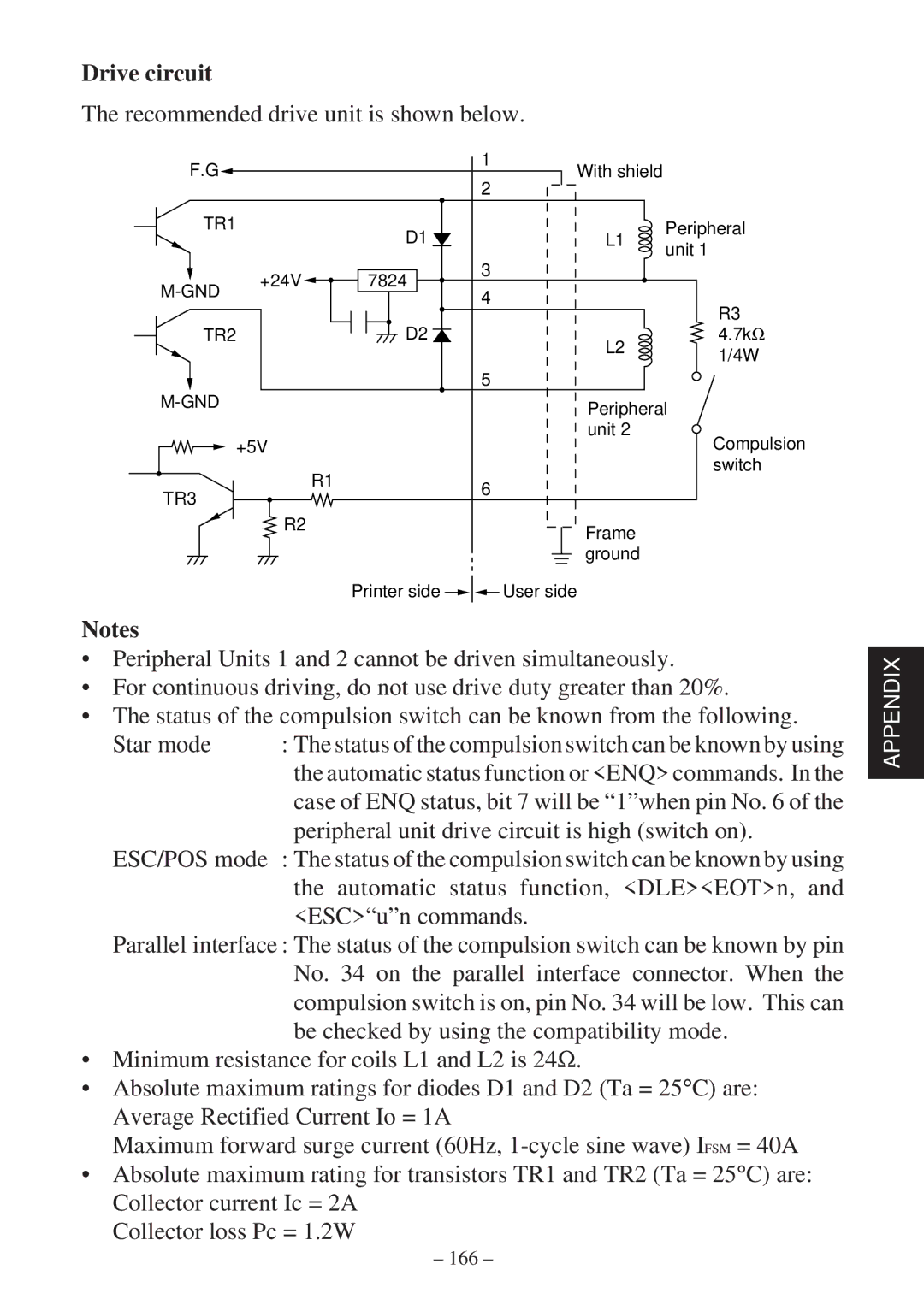
Drive circuit
The recommended drive unit is shown below.
F.G |
|
| 1 | With shield |
|
|
| 2 |
| ||
|
|
|
|
| |
TR1 |
| D1 |
| L1 | Peripheral |
|
|
| unit 1 | ||
|
|
|
|
| |
| +24V | 7824 | 3 |
|
|
4 |
|
| |||
|
|
|
| ||
|
|
|
| R3 | |
|
|
|
|
| |
TR2 |
| D2 |
| L2 | 4.7kΩ |
|
|
|
| 1/4W | |
|
|
|
|
| |
|
|
| 5 |
|
|
|
|
| Peripheral | ||
|
|
|
| ||
+5V |
|
| unit 2 | Compulsion | |
|
|
| |||
|
| R1 |
|
| switch |
TR3 |
| 6 |
|
| |
|
|
|
| ||
|
|
|
|
| |
| R2 |
|
| Frame |
|
|
|
|
|
| |
|
|
|
| ground |
|
|
| Printer side |
| User side |
|
Notes
•Peripheral Units 1 and 2 cannot be driven simultaneously.
•For continuous driving, do not use drive duty greater than 20%.
•The status of the compulsion switch can be known from the following.
Star mode | : The status of the compulsion switch can be known by using |
| the automatic status function or <ENQ> commands. In the |
| case of ENQ status, bit 7 will be “1”when pin No. 6 of the |
| peripheral unit drive circuit is high (switch on). |
ESC/POS mode | : The status of the compulsion switch can be known by using |
| the automatic status function, <DLE><EOT>n, and |
<ESC>“u”n commands.
Parallel interface : The status of the compulsion switch can be known by pin No. 34 on the parallel interface connector. When the compulsion switch is on, pin No. 34 will be low. This can be checked by using the compatibility mode.
•Minimum resistance for coils L1 and L2 is 24Ω.
•Absolute maximum ratings for diodes D1 and D2 (Ta = 25°C) are: Average Rectified Current Io = 1A
Maximum forward surge current (60Hz,
•Absolute maximum rating for transistors TR1 and TR2 (Ta = 25°C) are: Collector current Ic = 2A
Collector loss Pc = 1.2W
APPENDIX