Chapter 2: Technical Specifi cations and Installation
2.2.2 Connector and Header Descriptions (*AOC-SOZCR1)
Connector |
| Description |
J1 |
| Systerm Management Bus (I2C) (*See Page |
|
| I2C cable connection.) |
J2 |
| SCSI Mode (On: Enable) |
J3 |
| Serial ATA (SATA2) Mode (On: Enable) |
J4 |
| SAS Mode (On: Enable) |
J6 |
| Flash Firmware (On: Flashing Firmware.) |
2.2.3 SMB Connector and Pin Definitions (*AOC-SOZCR1)
SMB (I2C) |
|
|
|
|
|
|
|
|
|
|
| SMB (I2C) |
|
|
| ||
|
|
|
|
|
|
| ||
A System Management Bus header is |
|
| Pin Definitions (J1) |
|
|
| ||
located at J1. Connect the I2C cable |
|
|
|
|
|
|
|
|
|
| Pin | Definition |
|
|
| ||
here to utilize SMB on your |
|
| Number |
|
|
| ||
|
| 1 |
| Data |
|
|
| |
card (*See below). See the table on |
|
| 2 | Ground |
|
|
| |
|
| 3 |
| Clock |
|
|
| |
|
|
|
|
|
|
| ||
the right for pin defi nitions. |
|
|
|
|
|
|
|
|
|
|
|
|
|
|
| ||
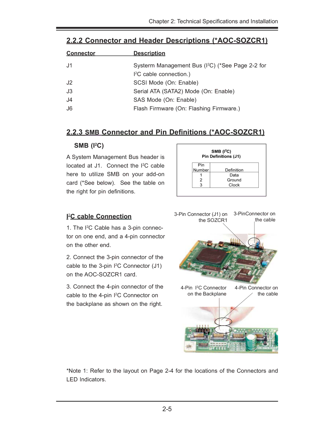
I2C cable Connection | ||||||||
| the cable | |||||||
|
|
| the SOZCR1 |
| ||||
1.The I2C Cable has a
2.Connect the
3.Connect the
on the Backplane | the cable |
*Note 1: Refer to the layout on Page