REAR PANEL (8 CHAN-
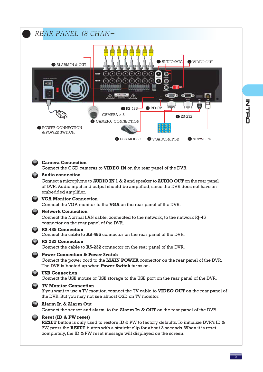
10ALARM IN & OUT
7POWER CONNECTION & POWER SWITCH
5
CAMERA × 8
1CAMERA CONNECTION
2 AUDIO/MIC 9 VIIDEO OUT
![]() RESET
RESET
6
8 USB MOUSE 3 VGA MONITOR | 4 NETWORK |
1
2
3
4
5
6
7
8
9
Camera Connection
Connect the CCD cameras to VIDEO IN on the rear panel of the DVR.
Audio connection
Connect a microphone to AUDIO IN 1 & 2 and speaker to AUDIO OUT on the rear panel of DVR. Audio input and output should be amplified, since the DVR does not have an embedded amplifier.
VGA Monitor Connection
Connect the VGA monitor to the VGA on the rear panel of the DVR.
Network Connection
Connect the Normal LAN cable, connected to the network, to the network
Connect the cable to
Connect the cable to
Power Connection & Power Switch
Connect the power cord to the MAIN POWER connector on the rear panel of the DVR. The DVR is booted up when Power Switch turns on.
USB Connection
Connect the USB mouse or USB storage to the USB port on the rear panel of the DVR.
TV Monitor Connection
If you want to use a TV monitor, connect the TV cable to VIDEO OUT on the rear panel of the DVR. But you may not see almost OSD on TV monitor.
10Alarm In & Alarm Out
Connect the sensor and alarm to the Alarm In & OUT on the rear panel of the DVR.
11Reset (ID & PW reset)
RESET button is only used to restore ID & PW to factory defaults. To initialize DVR’s ID & PW, press the RESET button with a straight clip for about 3 seconds.When it is reset completely, the ID & PW reset message will displayed on the screen.
5