Tandberg Codec C90
Table of Contents
What’s in this guide?
Codec C90 System Integrator Guide
Chapter
This chapter
Disclaimer
Intellectual Property Rights
Trademark
Patent Information
Safety Instructions
Water and Moisture
Environmental Issues
TANDBERG’s Environmental Policy
Getting started
Assemble your system
Optional
Using the Remote Control
Batteries
Using the Remote Control,
Call KEY
Turn on the system
Verify IP address settings
If you need to set a static IP address
Time zone settings
Verify your settings
Add the system to the network
Main monitor
About monitors
Dual monitors
Interfaces and sockets
Front panel
Video sockets Audio sockets Other sockets
Rear panel sockets overview
Codec C90 Rear Panel
API commands
Configure the video inputs
Administrator settings
Video Input Matrix
HD-SDI
Video inputs
Component 1-2 Y-Pr-Pb
Video input formats supported
Hdmi
DVI-I 3
DVI-I 2
Video outputs
Hdmi 1
Video output formats supported
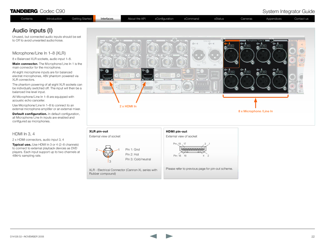
Microphone/Line In 1-8 XLR
Audio inputs
Hdmi In 3
Line In 1-4 RCA
RCA pin-out
Line Out 5-6 XLR
Audio outputs
Hdmi Out 1
Line Out 1-4 RCA
Line Out
Audio Signal Levels tables
Microphone Inputs 1 to XLR female
Volume control table
Audio signal levels,
Audio hardware information table
Network connectors
Ethernet interface
COM port
COM port and Camera Control port
Camera Control port
Power switch
Power
Power socket
Chassis grounding
Other connectors
Link
About the Tandberg API
About Telnet
Basic Principles
Tandberg API-Engine
Structuring of Information
Addressing Using XPath or Tandberg SimplePath Feedback
Using Tandberg SimplePath
Telnet/SSH login
Connecting to the codec
Accessing Xacli
Serial port login
Troubleshooting RS-232
Connecting to the codec,
Hardware & Cabling RS-232
Value types and formats
Formats for values types
Root commands
Status type commands
Main type of commands
Configuration type commands Command type commands
Special commands
About xConfiguration
XConfiguration ? XConfiguration help
XConfiguration Read
XConfiguration operations
XConfiguration Help
XConfiguration Write
About xCommand
XCommand ? XCommand help
XCommand Help
XCommand operations
XCommand Write
About xStatus commands
XStatus Read
Query status information
Address status information with xStatus
About xHistory command
Status operations and the return result parameters
About xFeedback
About xPreferences
Getxml
Tandberg XML API service
Bare-bone HTTP/HTTPS Access
Formputxml
XConfiguration type commands
Description of the xConfiguration commands
Audio settings
XConfiguration Audio Input Line 3. LoopSuppression On/Off
XConfiguration Audio Input Line 1. Level
XConfiguration Audio Input Line 1. Channel Left/Right/Mono
XConfiguration Audio Output Line 1. Mode On/Off
Camera settings
Conference settings
H323 Profile settings
Do not disturb setting
Network settings
Network services settings
XConfiguration NetworkServices Snmp SystemLocation S 0
XConfiguration NetworkServices Snmp CommunityName S 0
XConfiguration NetworkServices Snmp SystemContact S 0
XConfiguration NetworkServices Snmp HostIpAddress 1. S 0
Provisioning settings
Phone book settings
Serial port settings
SIP Profile settings
Standby settings
Video settings
System unit settings
Time zone setting
XConfiguration Video Input Source 1. CameraControl CameraId
XConfiguration Video OSD Mode On/Off
XConfiguration Video OSD Output
XConfiguration Video Input Source 1. Name S 0
XConfiguration Video Output Composite 5 Resolution PAL/NTSC
Experimental menu
XCommand type commands
XCommand Audio Microphones Mute
XCommands with parameters
Audio commands
XCommand Audio Microphones Unmute
XCommand Audio Sound Play
XCommand Audio LocalInput Update
XCommand Audio RemoteInput Update
XCommand Audio Sound Stop
Boot command
Call commands
Call Log commands
XCommand Camera CameraUpgrade
Camera commands
XCommand Camera BestView
XCommand Camera DirectIRControl
XCommand Camera PositionSet
XCommand Camera Ramp
XCommand Camera TriggerAutofocus
Dial command
XCommand Camera ReconfigureCameraChain
XCommand Dial
XCommand DTMFSend
Dtmf Send command
TString Send command
XCommand TStringSend
XCommand FarEndControl Preset Activate
Far End Control commands
XCommand FarEndControl Camera Move
XCommand FarEndControl Camera Stop
XCommand FarEndControl Source Select
Http Feedback commands
XCommand HttpFeedback Register
XCommand Key Click
Key commands
XCommand HttpFeedback Deregister
XCommand Key Press
XCommand Presentation Start
Presentation commands
XCommand Key Release
XCommand Presentation Stop
XCommand Preset Activate XCommand Preset Store
Preset commands
XCommand Preset Clear
SString Send command
Standby commands
Video command CamCtrlPip command
XCommand Video PictureLayoutSet XCommand CamCtrlPip
XCommand SystemUnit AdminPassword Set
System Unit commands
XCommand SystemUnit OptionKey Add
XCommand SystemUnit ReleaseKey Add
XCommand SystemUnit MenuPassword Validate
Phone book commands
XCommand Phonebook Contact Add
XCommand Phonebook ContactMethod Add
XCommand Phonebook Contact Modify
XCommand Phonebook Contact Delete
XCommand Phonebook ContactMethod Delete
XCommand Phonebook Group Add XCommand Phonebook Group Modify
XCommand Phonebook Group Delete
XCommand Phonebook Search
XCommand Phonebook SearchDetails
XCommand Experimental Audio LocalInput Remove
XCommand Experimental Audio LocalOutput Add
XCommand Experimental Audio LocalInput Add
XCommand Experimental Audio LocalInput AddConnector
XCommand Experimental Audio RemoteOutput Update
XCommand Experimental Audio LocalOutput ConnectInput
XCommand Experimental Audio LocalOutput DisconnectInput
XCommand Experimental Audio RemoteOutput ConnectInput
XCommand Experimental Camera DirectIRControl
XCommand Experimental Video Layout Frame Update
XCommand Experimental Video Layout Assign
XCommand Experimental SetLowLevel
XStatus type commands
Audio status
XStatus commands
Examples of returned status information
Call status
Camera status
Conference status
Diagnostics Call status
Codec C90
Number of bytes sent in this media channel
Codec C90
HTTPFeedback status
H323 Gatekeeper status
Media channels call status
Value space AACLD, G722, G7221, G711Mu
Network status
SIP status
System unit status
Example *s SystemUnit ProductId Tandberg Codec C90
Example *s SystemUnit Hardware AudioBoard SerialNumber TBD
Video status
Standby status
XStatus Video Output DVI 2, 4 Resolution RefreshRate
XStatus Video Output DVI 2, 4 Resolution Height
XStatus Video Output DVI 2, 4 Resolution Width
XStatus Video Input YPbPr 1. Connected
Cameras
Kensington lock
PrecisionHD 1080p camera
Hdmi and HD-SDI
Cascaded cameras
HD-SDI cable
Connecting the camera
Hdmi cable
Hdmi to DVI-D adapter
Using Best view
Best view-Face recognition
Video output formats
DIP switch settings for video output formats
Line voltage frequency
Cameras in daisy chain
Appendices
Software upgrade
Software upgrade procedure
How to upload the certificate
Certificates upload procedure
Upload certificates
XML files
Configuration
Command
Status
Log files
Debug log files
NTP Time Zone expressions
NTP Time Zone expressions,
GMT+0
Current RFCs and drafts supported in SIP
Supported RFCs in SIP
Media capabilities supported in SIP
Tandberg Remote Control TRC5
Arrows
Tandberg Remote Control TRC5 key map
Button codes Remote control TRC5
Tandberg Precision HD camera
PrecisionHD camera
Cascaded cameras
Kensington lock
CE Declaration for Codec C90
EC Declaration of conformity
China RoHS table
Tandberg Codec C90 dimensions
PrecisionHD 1080p camera dimensions
PrecisionHD camera dimensions
Technical specifications
Hdmi inputs, supported formats
ISO 9001 certificate is available upon request
Headquarters European Headquarters Tandberg