Teledyne 4060 manual 1 Internal Temperature Controllers, Gas Flow Control System

Models: 4060

1 79
Download 79 pages 47.82 Kb
Page 21
Image 21
Figure 2-1: Internal Temperature Controllers

Series 4060

Operational Theory


analyzer chassis. They are accessible by opening the front door of the analyzer.

Adjustments are made using the appropriate control on the front panel.

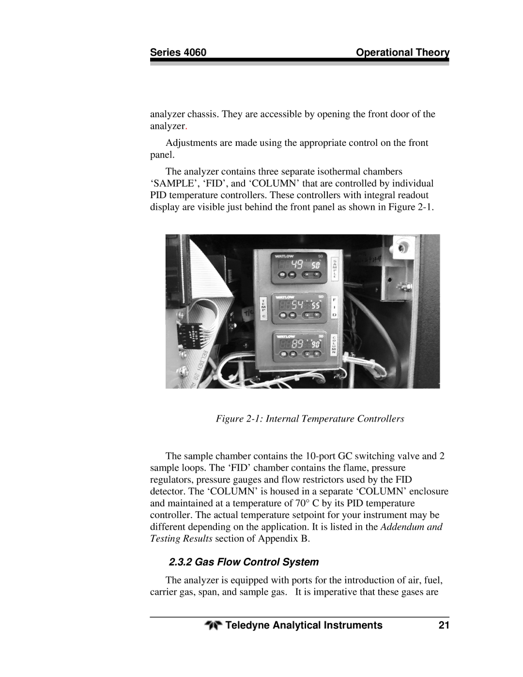
The analyzer contains three separate isothermal chambers ‘SAMPLE’, ‘FID’, and ‘COLUMN’ that are controlled by individual PID temperature controllers. These controllers with integral readout display are visible just behind the front panel as shown in Figure 2-1.

Figure 2-1: Internal Temperature Controllers

The sample chamber contains the 10-port GC switching valve and 2 sample loops. The ‘FID’ chamber contains the flame, pressure regulators, pressure gauges and flow restrictors used by the FID detector. The ‘COLUMN’ is housed in a separate ‘COLUMN’ enclosure and maintained at a temperature of 70° C by its PID temperature controller. The actual temperature setpoint for your instrument may be different depending on the application. It is listed in the Addendum and Testing Results section of Appendix B.

2.3.2 Gas Flow Control System

The analyzer is equipped with ports for the introduction of air, fuel, carrier gas, span, and sample gas. It is imperative that these gases are

Teledyne Analytical Instruments

21

Page 21
Image 21
Teledyne 4060 manual 1 Internal Temperature Controllers, Gas Flow Control System