Series 4060 | Operational Theory |
| | |
2.4.1 Electrometer-Amplifier
The collector cable is coupled directly to a coaxial fitting located on the electrometer-amplifier PC board. The PC board is located on the side panel next to but outside of the isothermal chamber. It consists of an electrometer amplifier and an operational amplifier. This circuit is a very high-gain, current-to-voltage converter circuit, having an input impedance measuring in the billions of ohms. It is static sensitive and highly susceptible to contamination. Special care must be taken in handling this PC board.
Refer to Section 5.5.3: Electrometer-Amplifier PC Board for more information concerning the electrometer-amplifier and the other printed circuits that follow.
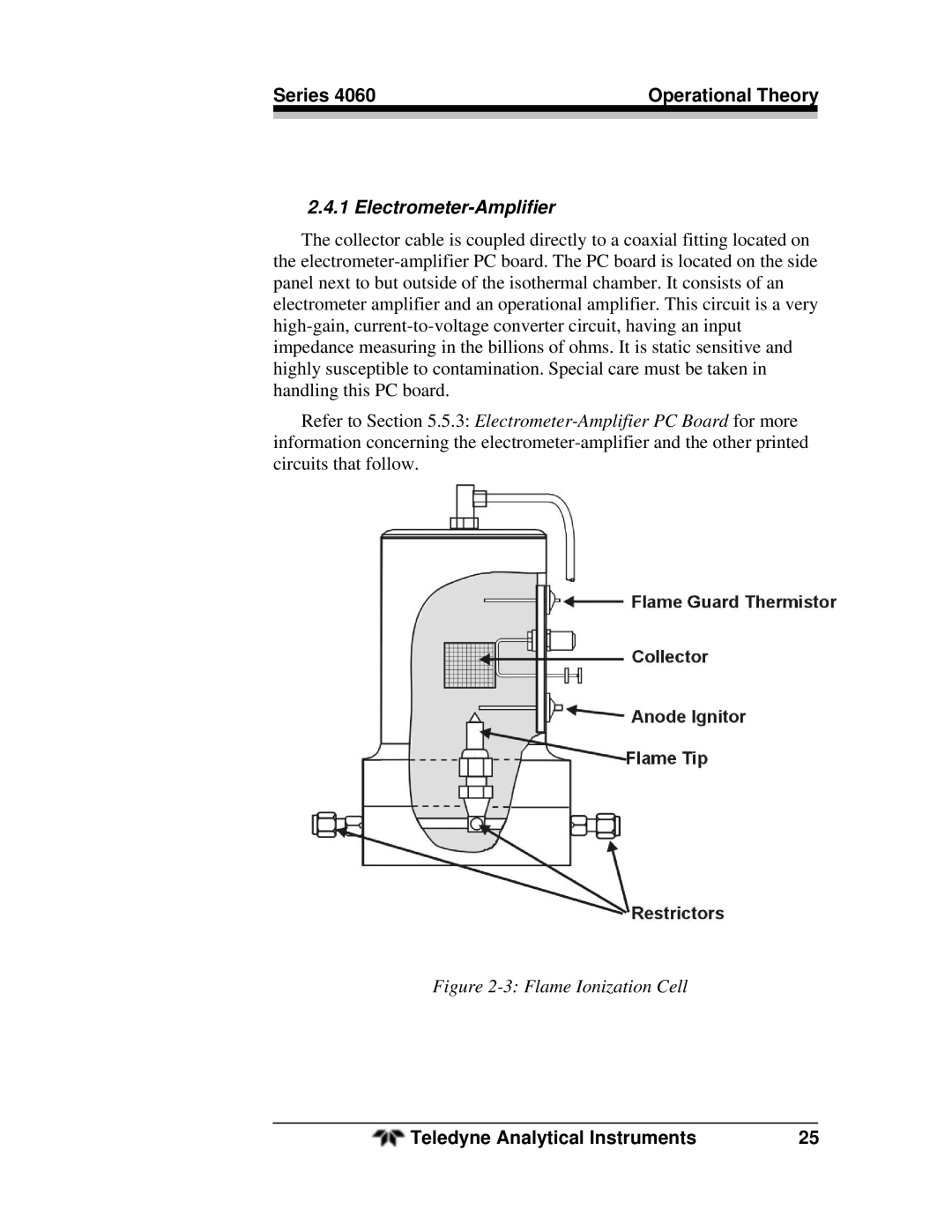
Figure 2-3: Flame Ionization Cell
Teledyne Analytical Instruments | 25 |