Series 4060 | Installation | |
|
|
|
For safe connections, no uninsulated wiring should be able to come in contact with fingers, tools or clothing during normal operation.
CAUTION: USE SHIELDED CABLES. ALSO, USE PLUGS THAT PROVIDE EXCELLENT EMI/RFI PROTECTION. THE PLUG CASE MUST BE CONNECTED TO THE CABLE SHIELD, AND IT MUST BE TIGHTLY FASTENED TO THE ANALYZER WITH ITS FASTENING SCREWS. ULTIMATELY, IT IS THE INSTALLER WHO ENSURES THAT THE CONNECTIONS PROVIDE ADEQUATE EMI/RFI SIELDING.
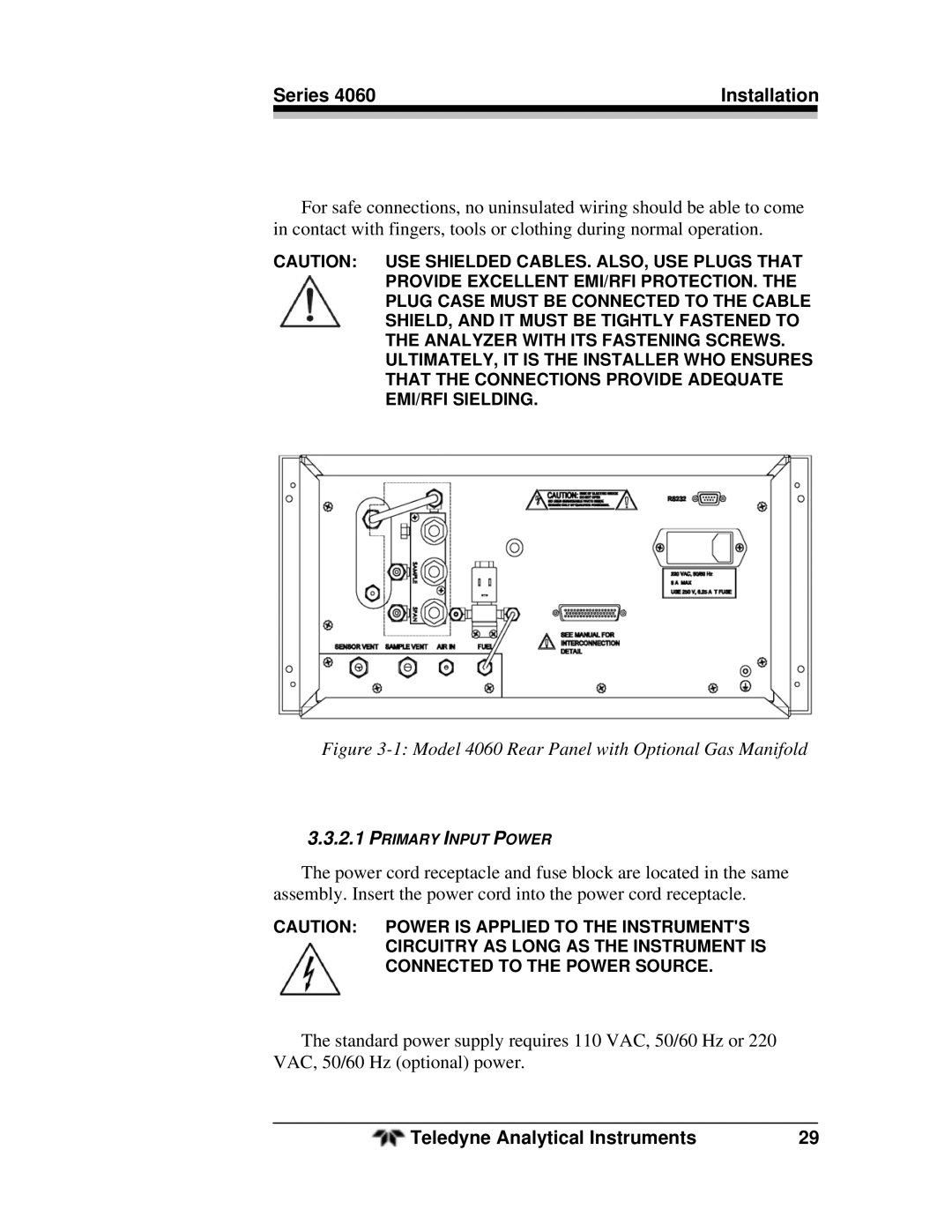
Figure 3-1: Model 4060 Rear Panel with Optional Gas Manifold
3.3.2.1PRIMARY INPUT POWER
The power cord receptacle and fuse block are located in the same assembly. Insert the power cord into the power cord receptacle.
CAUTION: POWER IS APPLIED TO THE INSTRUMENT'S CIRCUITRY AS LONG AS THE INSTRUMENT IS CONNECTED TO THE POWER SOURCE.
The standard power supply requires 110 VAC, 50/60 Hz or 220 VAC, 50/60 Hz (optional) power.
Teledyne Analytical Instruments | 29 |