Installation | Series 4060 | |
|
|
|
|
|
|
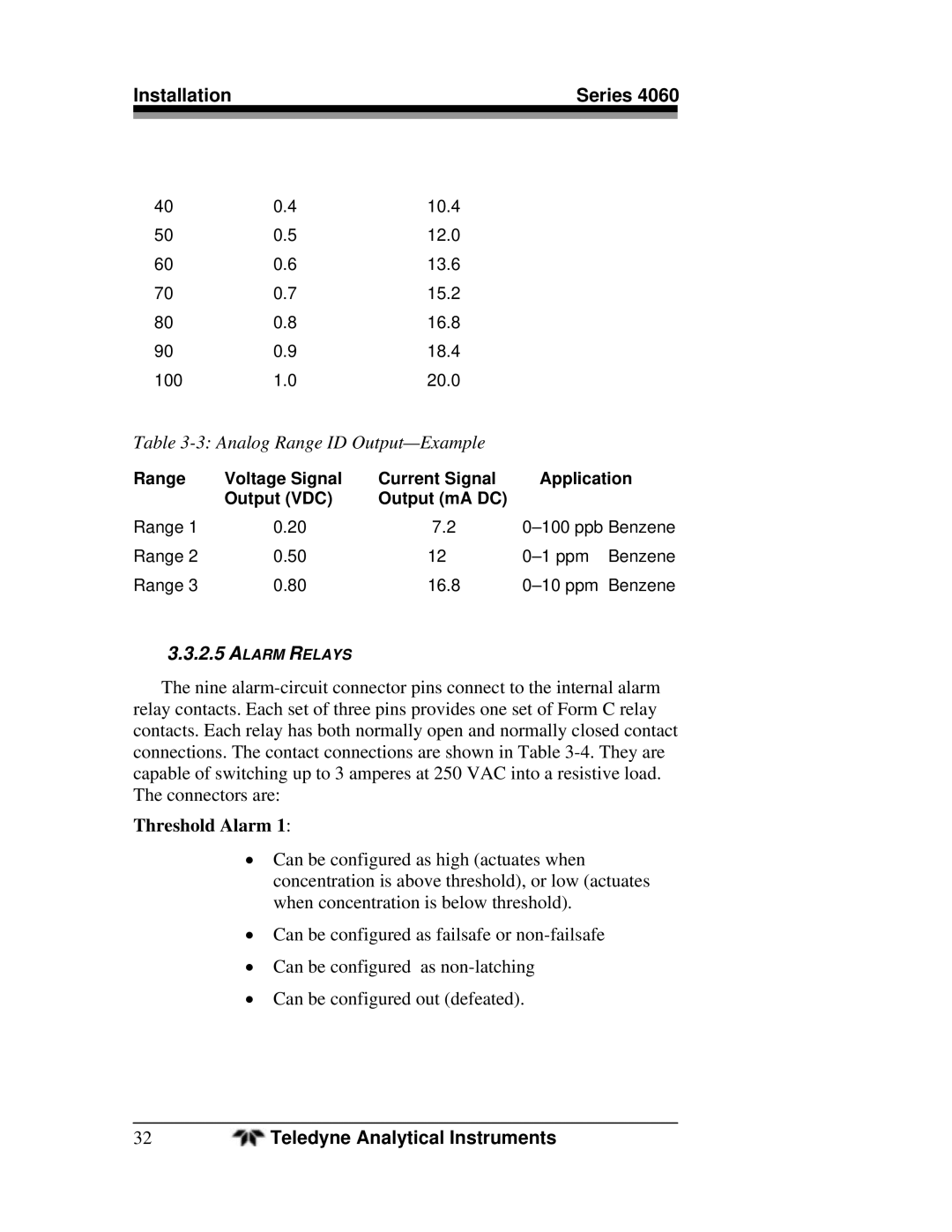
40 | 0.4 | 10.4 |
50 | 0.5 | 12.0 |
60 | 0.6 | 13.6 |
70 | 0.7 | 15.2 |
80 | 0.8 | 16.8 |
90 | 0.9 | 18.4 |
100 | 1.0 | 20.0 |
Table 3-3: Analog Range ID Output—Example
Range | Voltage Signal | Current Signal | Application |
| Output (VDC) | Output (mA DC) |
|
Range 1 | 0.20 | 7.2 | |
Range 2 | 0.50 | 12 | |
Range 3 | 0.80 | 16.8 |
3.3.2.5ALARM RELAYS
The nine
Threshold Alarm 1:
Can be configured as high (actuates when concentration is above threshold), or low (actuates when concentration is below threshold).
Can be configured as failsafe or
Can be configured as
Can be configured out (defeated).
32 | Teledyne Analytical Instruments |