Installation | Series 4060 | |
|
|
|
|
|
|
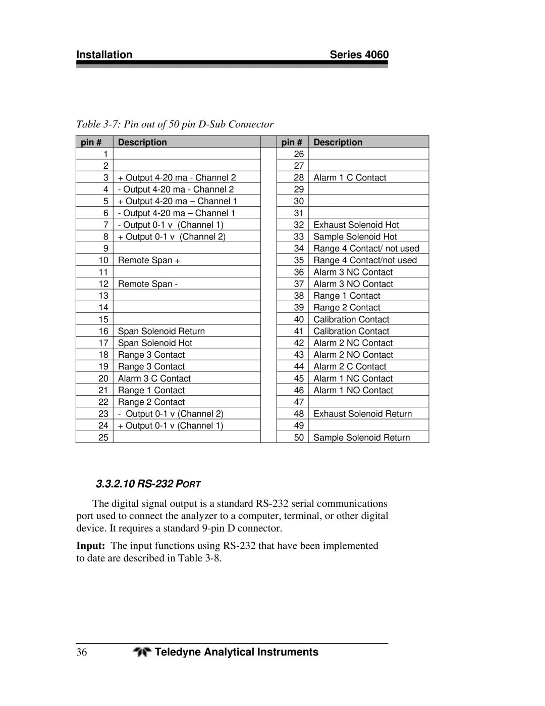
Table 3-7: Pin out of 50 pin D-Sub Connector
pin # | Description |
| pin # | Description |
1 |
|
| 26 |
|
2 |
|
| 27 |
|
3 | + Output |
| 28 | Alarm 1 C Contact |
4 | - Output |
| 29 |
|
5 | + Output |
| 30 |
|
6 | - Output |
| 31 |
|
7 | - Output |
| 32 | Exhaust Solenoid Hot |
8 | + Output |
| 33 | Sample Solenoid Hot |
9 |
|
| 34 | Range 4 Contact/ not used |
10 | Remote Span + |
| 35 | Range 4 Contact/not used |
11 |
|
| 36 | Alarm 3 NC Contact |
12 | Remote Span - |
| 37 | Alarm 3 NO Contact |
13 |
|
| 38 | Range 1 Contact |
14 |
|
| 39 | Range 2 Contact |
15 |
|
| 40 | Calibration Contact |
16 | Span Solenoid Return |
| 41 | Calibration Contact |
17 | Span Solenoid Hot |
| 42 | Alarm 2 NC Contact |
18 | Range 3 Contact |
| 43 | Alarm 2 NO Contact |
19 | Range 3 Contact |
| 44 | Alarm 2 C Contact |
20 | Alarm 3 C Contact |
| 45 | Alarm 1 NC Contact |
21 | Range 1 Contact |
| 46 | Alarm 1 NO Contact |
22 | Range 2 Contact |
| 47 |
|
23 | - Output |
| 48 | Exhaust Solenoid Return |
24 | + Output |
| 49 |
|
25 |
|
| 50 | Sample Solenoid Return |
3.3.2.10 RS-232 PORT
The digital signal output is a standard
Input: The input functions using
36 | Teledyne Analytical Instruments |