Installation | Series 4060 | |
|
|
|
|
|
|
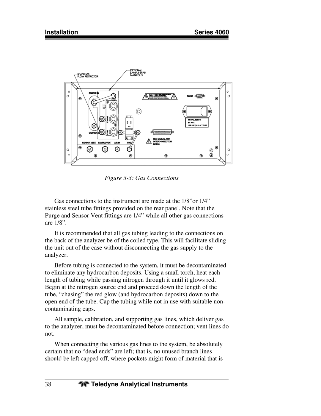
Figure 3-3: Gas Connections
Gas connections to the instrument are made at the 1/8”or 1/4” stainless steel tube fittings provided on the rear panel. Note that the Purge and Sensor Vent fittings are 1/4” while all other gas connections are 1/8”.
It is recommended that all gas tubing leading to the connections on the back of the analyzer be of the coiled type. This will facilitate sliding the unit out of the case without disconnecting the gas supply to the analyzer.
Before tubing is connected to the system, it must be decontaminated to eliminate any hydrocarbon deposits. Using a small torch, heat each length of tubing while passing nitrogen through it until it glows red. Begin at the nitrogen source end and proceed down the length of the tube, “chasing” the red glow (and hydrocarbon deposits) down to the open end of the tube. Cap the tubing while not in use with suitable non- contaminating caps.
All sample, calibration, and supporting gas lines, which deliver gas to the analyzer, must be decontaminated before connection; vent lines do not.
When connecting the various gas lines to the system, be absolutely certain that no “dead ends” are left; that is, no unused branch lines should be left capped off, where pockets might form of material that is
38 | Teledyne Analytical Instruments |