Manuals
/
Teledyne
/
TV and Video
/
TV Converter Box
Teledyne
4060
manual
Typical Piping Diagram for the Model
Models:
4060
1
23
79
79
Download
79 pages
47.82 Kb
20
21
22
23
24
25
26
27
Troubleshooting
Install
Parts list
Threshold Alarm
Password
Default Parameters
Maintenance
System Self-Diagnostic Test
Setting up an AUTO-CAL
Commands via RS-232 Input
Page 23
Image 23
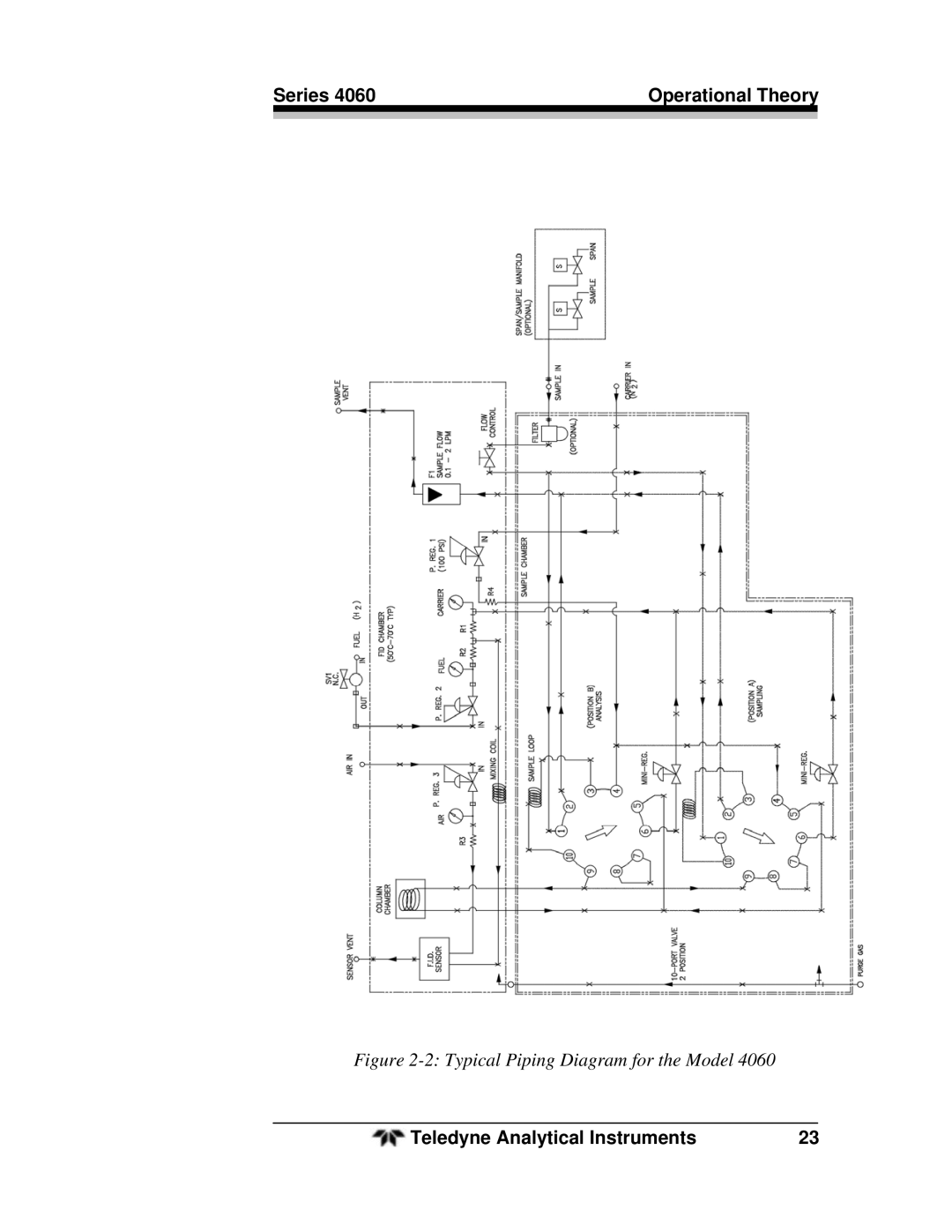
Series 4060
Operational Theory
Figure
2-2:
Typical Piping Diagram for the Model 4060
Teledyne Analytical Instruments
23
Page 22
Page 24
Page 23
Image 23
Page 22
Page 24
Contents
Series
Teledyne Analytical Instruments
Series
Teledyne Analytical Instruments Iii
Safety Messages
Series
Combustible GAS Usage
Additional Safety Information
Series
Teledyne Analytical Instruments Vii
Procedure for Removal of Internal Inaccessible Shock Hazards
Viii
Table of Contents
Operation
Maintenance & Troubleshooting
Appendix B
Appendix
Teledyne Analytical Instruments Xiii
List of Figures
List of Tables
Series Introduction
Main Features of the Analyzer
Introduction
Introduction Series
Principle of Operation
Analyzer Description
Model 4060 Front Panel Interface
Applications
Series Operational Theory
Operational Theory
Introduction
Modes of Operation
Sample System
Analyzer Subsystems
Operational Theory Series
Gas Flow Control System
Internal Temperature Controllers
Flame Ionization Detection Cell
Fuel and Blanket Air Systems
Typical Piping Diagram for the Model
Detection Cell
Flame Ionization Cell
Electrometer-Amplifier
Flame Ignition Circuit
Anode Power Supply
Flame Guard Circuit
Mounting the Analyzer
Installation
Series Installation
Unpacking the Analyzer
Electronic Connections
Installation Series
Electrical Power Connections
User Connections
Model 4060 Rear Panel with Optional Gas Manifold
Equipment Interface Connector Pin Arrangement
Pin Function
Threshold Alarm
System Alarm
Remote Calibration Connections
Range ID Relay Connections
2.10 RS-232 Port
Pin out of 50 pin D-Sub Connector
Gas Connections
Commands via RS-232 Input
Gas Connections
Less than 0.5 PPM
Placing the System in Operation
Series Operation
Operation
Equipment
Operation Series
Preliminary Power-Off Check List
Activating the Support Gases
Span Gas
Flame Ignition
1 Air
Carrier Gas
Ignition and/or Flame Guard Circuit Failure
Sample Pump
Analyzer Operation
Verification of the Flame Guard Circuit
Series Operation
Style Conventions
Default Parameters
Enter
Navigation and Data Entry
Menu Structure
Escape
Main Menus
Span
Model Screen
System Self-Diagnostic Test
ALT-SPAN
Alarms Function
AL-1 Defeated AL-1 High AL-1 NON-FAILSAFE AL-1 NON-LATCHING
Operation Series
Range Function
Analog Output Adjustment
Changing Stream
Setting up an AUTO-CAL
Linearization
Autocal Password
Timing
Group Setup
Password Protection
Entering a Password
Enter NEW Password Screen
Logging Out
Repeat Password Entry Screen
Standby
Series Operation
Operation Series Teledyne Analytical Instruments
Series Maintenance
Maintenance & Troubleshooting
Anode Voltage Check
Maintenance Series
Measuring Circuit Electrical Checks
Electronic Stability
Printed Circuit Board Replacement
Collector Cable
Temperature Control Electronic Check
Ignition and/or Flame Guard Circuit Checks
Sampling System
Printed Circuit Board Descriptions
Flame Guard and Anode Power Supply PCB
Proportional Temperature Controller PCB
Electrometer-Amplifier PCB
Maintenance Series
Series Appendix
Specifications and Initial Settings
Appendix
Analytical Instruments
Recommended Spare Parts List
Appendix Series
PC Board Assemblies
Drawing List
Appendix Series Teledyne Analytical Instruments
Appendix B
B1 Addendum and Testing Results
Top
Page
Image
Contents