www.ti.com
Peripheral Architecture
2.1.2Clock Configuration
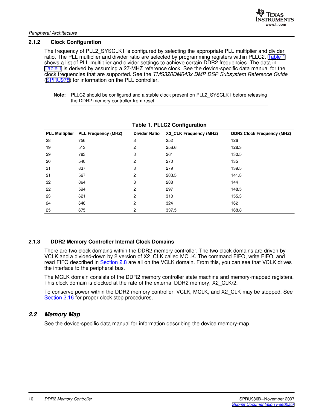
The frequency of PLL2_SYSCLK1 is configured by selecting the appropriate PLL multiplier and divider ratio. The PLL multiplier and divider ratio are selected by programming registers within PLLC2. Table 1 shows a list of PLL multiplier and divider settings to achieve certain DDR2 frequencies. The data in Table 1 is derived by assuming a
Note: PLLC2 should be configured and a stable clock present on PLL2_SYSCLK1 before releasing the DDR2 memory controller from reset.
Table 1. PLLC2 Configuration
PLL Multiplier | PLL Frequency (MHZ) | Divider Ratio | X2_CLK Frequency (MHZ) | DDR2 Clock Frequency (MHZ) |
28 | 756 | 3 | 252 | 126 |
19 | 513 | 2 | 256.6 | 128.3 |
29 | 783 | 3 | 261 | 130.5 |
20 | 540 | 2 | 270 | 135 |
31 | 837 | 3 | 279 | 139.5 |
21 | 567 | 2 | 283.5 | 141.8 |
32 | 864 | 3 | 288 | 144 |
22 | 594 | 2 | 297 | 148.5 |
23 | 621 | 2 | 310 | 155.3 |
24 | 648 | 2 | 324 | 162 |
25 | 675 | 2 | 337.5 | 168.8 |
2.1.3DDR2 Memory Controller Internal Clock Domains
There are two clock domains within the DDR2 memory controller. The two clock domains are driven by VCLK and a
The MCLK domain consists of the DDR2 memory controller state machine and
To conserve power within the DDR2 memory controller, VCLK, MCLK, and X2_CLK may be stopped. See Section 2.16 for proper clock stop procedures.
2.2Memory Map
See the
10 | DDR2 Memory Controller |