www.ti.com
Introduction
1.3Functional Block Diagram
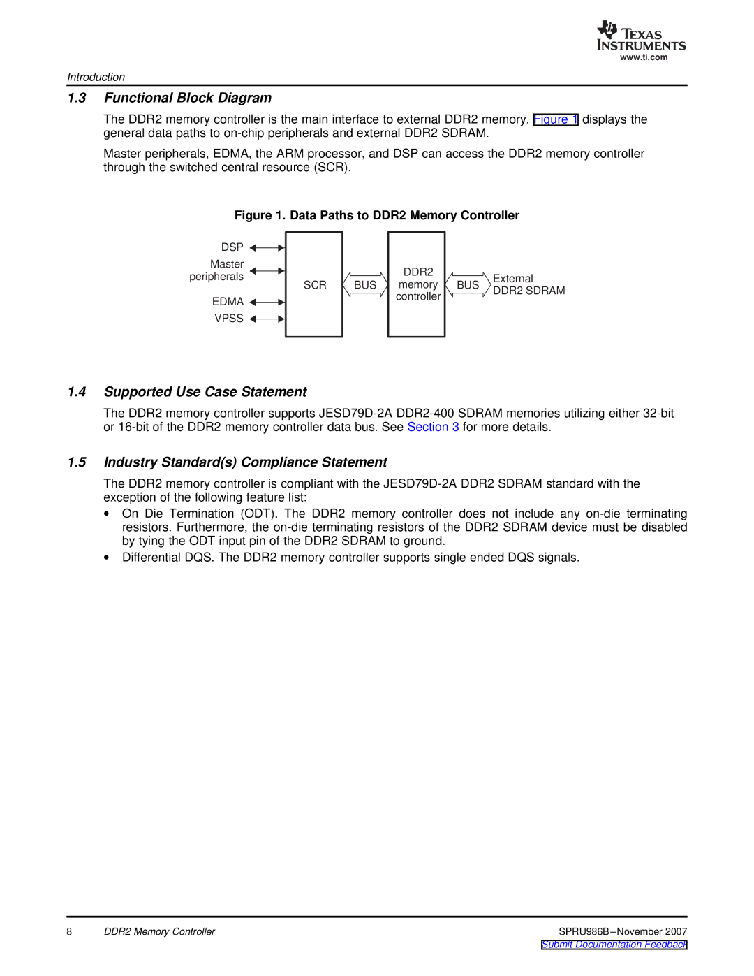
The DDR2 memory controller is the main interface to external DDR2 memory. Figure 1 displays the general data paths to
Master peripherals, EDMA, the ARM processor, and DSP can access the DDR2 memory controller through the switched central resource (SCR).
Figure 1. Data Paths to DDR2 Memory Controller
DSP ![]()
Master peripherals
EDMA ![]()
![]() VPSS
VPSS ![]()
![]()
SCR
![]() BUS
BUS ![]()
DDR2
memory controller
![]()
![]() External
External
BUS DDR2 SDRAM
1.4Supported Use Case Statement
The DDR2 memory controller supports
1.5Industry Standard(s) Compliance Statement
The DDR2 memory controller is compliant with the
∙On Die Termination (ODT). The DDR2 memory controller does not include any
∙Differential DQS. The DDR2 memory controller supports single ended DQS signals.
8 | DDR2 Memory Controller |
