www.ti.com
DDR2 Memory Controller Registers
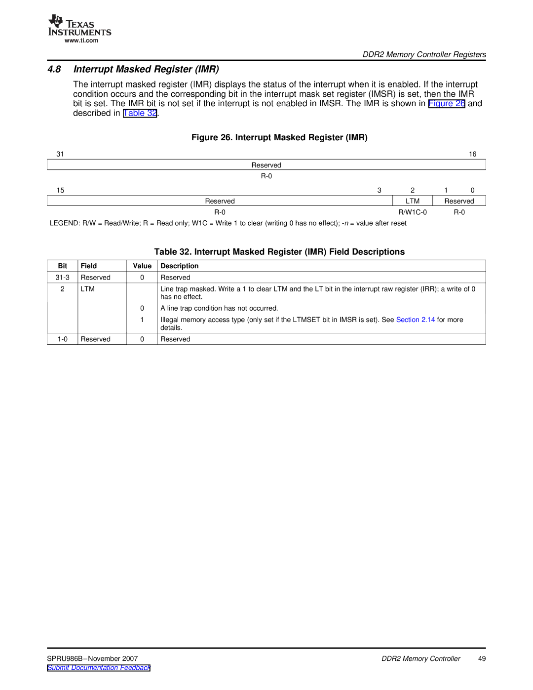
4.8Interrupt Masked Register (IMR)
The interrupt masked register (IMR) displays the status of the interrupt when it is enabled. If the interrupt condition occurs and the corresponding bit in the interrupt mask set register (IMSR) is set, then the IMR bit is set. The IMR bit is not set if the interrupt is not enabled in IMSR. The IMR is shown in Figure 26 and described in Table 32.
Figure 26. Interrupt Masked Register (IMR)
31 |
|
|
| 16 |
| Reserved |
|
|
|
|
|
|
| |
15 | 3 | 2 | 1 | 0 |
Reserved |
| LTM | Reserved | |
|
| |||
LEGEND: R/W = Read/Write; R = Read only; W1C = Write 1 to clear (writing 0 has no effect); |
|
| ||
|
|
| Table 32. Interrupt Masked Register (IMR) Field Descriptions |
Bit | Field | Value | Description |
Reserved | 0 | Reserved | |
2 | LTM |
| Line trap masked. Write a 1 to clear LTM and the LT bit in the interrupt raw register (IRR); a write of 0 |
|
|
| has no effect. |
|
| 0 | A line trap condition has not occurred. |
|
| 1 | Illegal memory access type (only set if the LTMSET bit in IMSR is set). See Section 2.14 for more |
|
|
| details. |
Reserved | 0 | Reserved |
DDR2 Memory Controller | 49 | |
Submit Documentation Feedback |
|
|