Peripheral Architecture | www.ti.com |
2 Peripheral Architecture
2.1Clock Generation and Control
The UART bit clock is sourced from the PLLC1 AUXCLK. It supports up to 128 kbps maximum data rate.
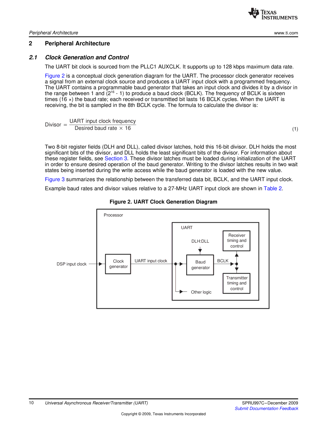
Figure 2 is a conceptual clock generation diagram for the UART. The processor clock generator receives a signal from an external clock source and produces a UART input clock with a programmed frequency. The UART contains a programmable baud generator that takes an input clock and divides it by a divisor in the range between 1 and (216 - 1) to produce a baud clock (BCLK). The frequency of BCLK is sixteen times (16 ×) the baud rate; each received or transmitted bit lasts 16 BCLK cycles. When the UART is receiving, the bit is sampled in the 8th BCLK cycle. The formula to calculate the divisor is:
UART input clock frequency |
|
Divisor + Desired baud rate 16 | (1) |
Two 8-bit register fields (DLH and DLL), called divisor latches, hold this 16-bit divisor. DLH holds the most significant bits of the divisor, and DLL holds the least significant bits of the divisor. For information about these register fields, see Section 3. These divisor latches must be loaded during initialization of the UART in order to ensure desired operation of the baud generator. Writing to the divisor latches results in two wait states being inserted during the write access while the baud generator is loaded with the new value.
Figure 3 summarizes the relationship between the transferred data bit, BCLK, and the UART input clock.
Example baud rates and divisor values relative to a 27-MHz UART input clock are shown in Table 2.
DSP input clock
Figure 2. UART Clock Generation Diagram
Processor |
|
|
|
|
| UART |
|
|
|
| Receiver |
|
| DLH:DLL | timing and |
|
|
| control |
Clock | UART input clock | Baud | BCLK |
generator |
| generator |
|
|
|
| Transmitter |
|
|
| timing and |
|
| Other logic | control |
|
|
|
10 | Universal Asynchronous Receiver/Transmitter (UART) | SPRU997C |
|
| Submit Documentation Feedback |
Copyright © 2009, Texas Instruments Incorporated