Registerswww.ti.com
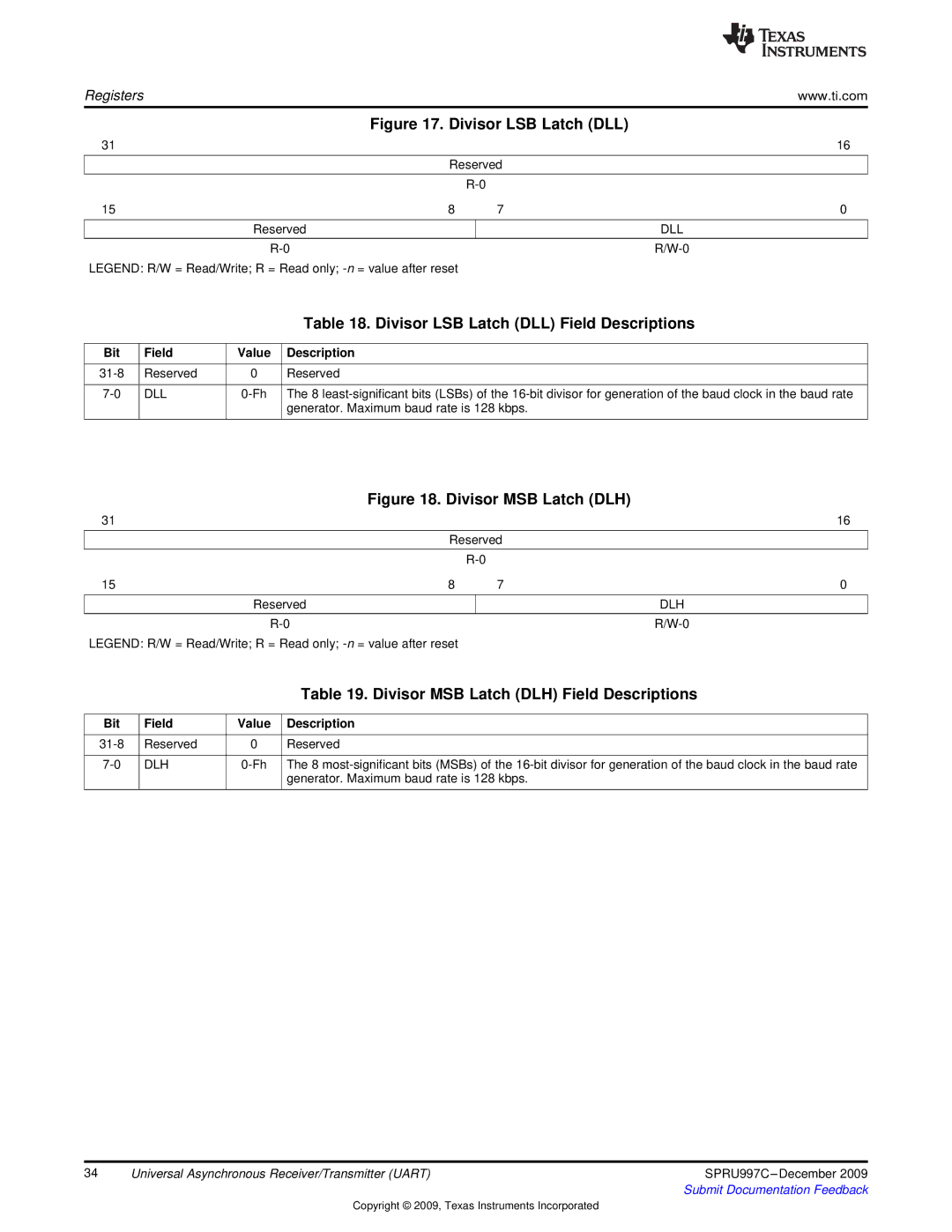
Figure 17. Divisor LSB Latch (DLL)
31 |
|
|
| 16 |
| Reserved |
| ||
|
|
|
| |
|
|
| ||
15 | 8 | 7 | 0 | |
|
|
|
|
|
| Reserved |
|
| DLL |
|
|
|
|
|
|
|
| ||
LEGEND: R/W = Read/Write; R = Read only;
|
|
| Table 18. Divisor LSB Latch (DLL) Field Descriptions |
|
|
|
|
Bit | Field | Value | Description |
|
|
|
|
Reserved | 0 | Reserved | |
|
|
|
|
DLL | The 8 | ||
|
|
| generator. Maximum baud rate is 128 kbps. |
|
|
|
|
Figure 18. Divisor MSB Latch (DLH)
31 |
|
|
| 16 |
| Reserved |
| ||
|
|
|
| |
|
|
| ||
15 | 8 | 7 | 0 | |
|
|
|
|
|
| Reserved |
|
| DLH |
|
|
|
|
|
|
|
| ||
LEGEND: R/W = Read/Write; R = Read only;
|
|
| Table 19. Divisor MSB Latch (DLH) Field Descriptions |
|
|
|
|
Bit | Field | Value | Description |
|
|
|
|
Reserved | 0 | Reserved | |
|
|
|
|
DLH | The 8 | ||
|
|
| generator. Maximum baud rate is 128 kbps. |
|
|
|
|
34 | Universal Asynchronous Receiver/Transmitter (UART) | SPRU997C |
|
| Submit Documentation Feedback |
Copyright © 2009, Texas Instruments Incorporated