www.ti.comRegisters
|
|
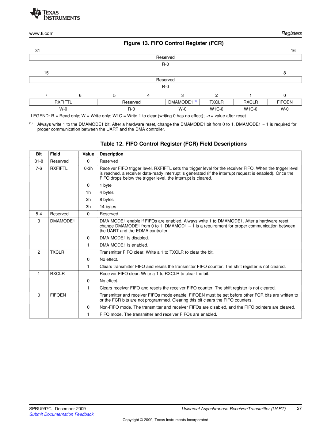
| Figure 13. FIFO Control Register (FCR) |
|
| |||
31 |
|
|
|
|
|
|
| 16 |
|
|
|
|
|
|
|
| |
|
|
|
| Reserved |
|
|
| |
|
|
|
|
|
|
|
| |
|
|
|
|
|
|
| ||
15 |
|
|
|
|
|
|
| 8 |
|
|
|
|
|
|
|
| |
|
|
|
| Reserved |
|
|
| |
|
|
|
|
|
|
|
| |
|
|
|
|
|
|
| ||
7 | 6 | 5 | 4 | 3 | 2 | 1 | 0 | |
|
|
|
|
|
|
|
|
|
| RXFIFTL |
| Reserved |
| DMAMODE1(1) | TXCLR | RXCLR | FIFOEN |
|
|
| ||||||
LEGEND: R = Read only; W = Write only; W1C = Write 1 to clear (writing 0 has no effect);
(1)Always write 1 to the DMAMODE1 bit. After a hardware reset, change the DMAMODE1 bit from 0 to 1. DMAMODE1 = 1 is required for proper communication between the UART and the DMA controller.
|
|
| Table 12. FIFO Control Register (FCR) Field Descriptions |
|
|
|
|
Bit | Field | Value | Description |
|
|
|
|
Reserved | 0 | Reserved | |
|
|
|
|
RXFIFTL | Receiver FIFO trigger level. RXFIFTL sets the trigger level for the receiver FIFO. When the trigger level | ||
|
|
| is reached, a receiver |
|
|
| FIFO drops below the trigger level, the interrupt is cleared. |
|
| 0 | 1 byte |
|
| 1h | 4 bytes |
|
| 2h | 8 bytes |
|
| 3h | 14 bytes |
|
|
|
|
Reserved | 0 | Reserved | |
|
|
|
|
3 | DMAMODE1 |
| DMA MODE1 enable if FIFOs are enabled. Always write 1 to DMAMODE1. After a hardware reset, |
|
|
| change DMAMODE1 from 0 to 1. DMAMOD1 = 1 is a requirement for proper communication between |
|
|
| the UART and the EDMA controller. |
|
| 0 | DMA MODE1 is disabled. |
|
| 1 | DMA MODE1 is enabled. |
|
|
|
|
2 | TXCLR |
| Transmitter FIFO clear. Write a 1 to TXCLR to clear the bit. |
|
| 0 | No effect. |
|
| 1 | Clears transmitter FIFO and resets the transmitter FIFO counter. The shift register is not cleared. |
|
|
|
|
1 | RXCLR |
| Receiver FIFO clear. Write a 1 to RXCLR to clear the bit. |
|
| 0 | No effect. |
|
| 1 | Clears receiver FIFO and resets the receiver FIFO counter. The shift register is not cleared. |
|
|
|
|
0 | FIFOEN |
| Transmitter and receiver FIFOs mode enable. FIFOEN must be set before other FCR bits are written to |
|
|
| or the FCR bits are not programmed. Clearing this bit clears the FIFO counters. |
|
| 0 | |
|
| 1 | FIFO mode. The transmitter and receiver FIFOs are enabled. |
|
|
|
|
SPRU997C | Universal Asynchronous Receiver/Transmitter (UART) | 27 |
Submit Documentation Feedback |
|
|
Copyright © 2009, Texas Instruments Incorporated