Registers | www.ti.com |
3.7Modem Control Register (MCR)
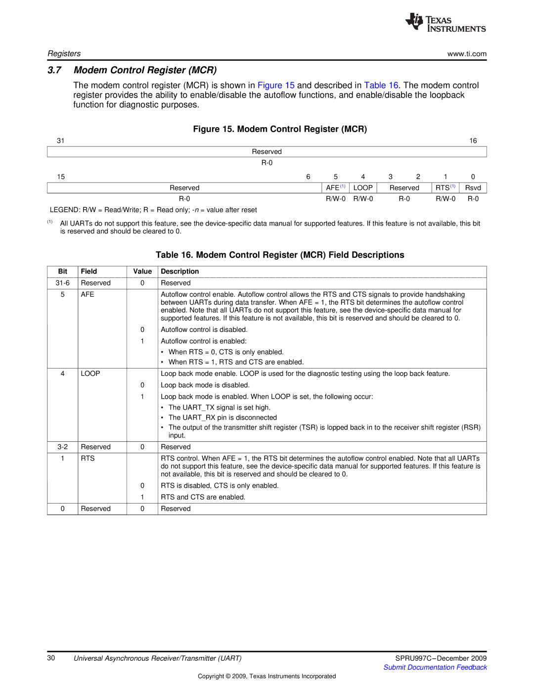
The modem control register (MCR) is shown in Figure 15 and described in Table 16. The modem control register provides the ability to enable/disable the autoflow functions, and enable/disable the loopback function for diagnostic purposes.
Figure 15. Modem Control Register (MCR)
31 |
|
|
|
|
|
| 16 |
| Reserved |
|
|
|
|
|
|
|
|
|
|
|
|
|
|
|
|
|
|
|
|
| |
15 | 6 | 5 | 4 | 3 | 2 | 1 | 0 |
|
|
|
|
|
|
| |
Reserved |
| AFE(1) | LOOP | Reserved | RTS(1) | Rsvd | |
|
| ||||||
LEGEND: R/W = Read/Write; R = Read only;
(1)All UARTs do not support this feature, see the
|
|
| Table 16. Modem Control Register (MCR) Field Descriptions | |
|
|
|
|
|
Bit | Field | Value |
| Description |
|
|
|
|
|
Reserved | 0 |
| Reserved | |
|
|
|
|
|
5 | AFE |
|
| Autoflow control enable. Autoflow control allows the RTS and CTS signals to provide handshaking |
|
|
|
| between UARTs during data transfer. When AFE = 1, the RTS bit determines the autoflow control |
|
|
|
| enabled. Note that all UARTs do not support this feature, see the |
|
|
|
| supported features. If this feature is not available, this bit is reserved and should be cleared to 0. |
|
| 0 |
| Autoflow control is disabled. |
|
| 1 |
| Autoflow control is enabled: |
|
|
|
| • When RTS = 0, CTS is only enabled. |
|
|
|
| • When RTS = 1, RTS and CTS are enabled. |
|
|
|
|
|
4 | LOOP |
|
| Loop back mode enable. LOOP is used for the diagnostic testing using the loop back feature. |
|
| 0 |
| Loop back mode is disabled. |
|
| 1 |
| Loop back mode is enabled. When LOOP is set, the following occur: |
|
|
|
| • The UART_TX signal is set high. |
|
|
|
| • The UART_RX pin is disconnected |
|
|
|
| • The output of the transmitter shift register (TSR) is lopped back in to the receiver shift register (RSR) |
|
|
|
| input. |
|
|
|
|
|
Reserved | 0 |
| Reserved | |
|
|
|
|
|
1 | RTS |
|
| RTS control. When AFE = 1, the RTS bit determines the autoflow control enabled. Note that all UARTs |
|
|
|
| do not support this feature, see the |
|
|
|
| not available, this bit is reserved and should be cleared to 0. |
|
| 0 |
| RTS is disabled, CTS is only enabled. |
|
| 1 |
| RTS and CTS are enabled. |
|
|
|
|
|
0 | Reserved | 0 |
| Reserved |
|
|
|
|
|
30 | Universal Asynchronous Receiver/Transmitter (UART) | SPRU997C |
|
| Submit Documentation Feedback |
Copyright © 2009, Texas Instruments Incorporated