www.ti.comRegisters
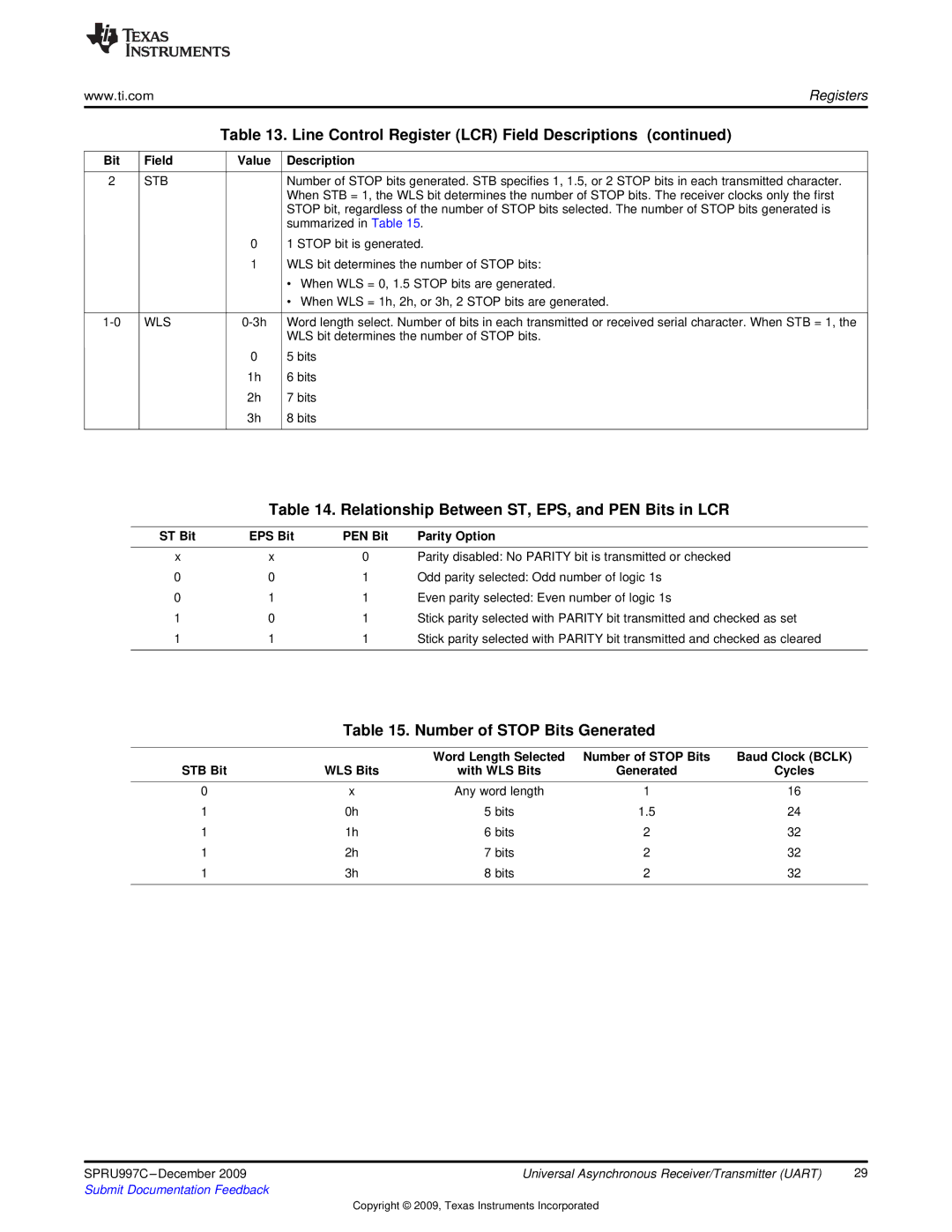
Table 13. Line Control Register (LCR) Field Descriptions (continued)
Bit | Field | Value | Description |
|
|
|
|
2 | STB |
| Number of STOP bits generated. STB specifies 1, 1.5, or 2 STOP bits in each transmitted character. |
|
|
| When STB = 1, the WLS bit determines the number of STOP bits. The receiver clocks only the first |
|
|
| STOP bit, regardless of the number of STOP bits selected. The number of STOP bits generated is |
|
|
| summarized in Table 15. |
|
| 0 | 1 STOP bit is generated. |
|
| 1 | WLS bit determines the number of STOP bits: |
|
|
| • When WLS = 0, 1.5 STOP bits are generated. |
|
|
| • When WLS = 1h, 2h, or 3h, 2 STOP bits are generated. |
|
|
|
|
WLS | Word length select. Number of bits in each transmitted or received serial character. When STB = 1, the | ||
|
|
| WLS bit determines the number of STOP bits. |
|
| 0 | 5 bits |
|
| 1h | 6 bits |
|
| 2h | 7 bits |
|
| 3h | 8 bits |
|
|
|
|
Table 14. Relationship Between ST, EPS, and PEN Bits in LCR
ST Bit | EPS Bit | PEN Bit | Parity Option |
x | x | 0 | Parity disabled: No PARITY bit is transmitted or checked |
0 | 0 | 1 | Odd parity selected: Odd number of logic 1s |
0 | 1 | 1 | Even parity selected: Even number of logic 1s |
1 | 0 | 1 | Stick parity selected with PARITY bit transmitted and checked as set |
1 | 1 | 1 | Stick parity selected with PARITY bit transmitted and checked as cleared |
|
|
|
|
Table 15. Number of STOP Bits Generated
|
| Word Length Selected | Number of STOP Bits | Baud Clock (BCLK) |
STB Bit | WLS Bits | with WLS Bits | Generated | Cycles |
|
|
|
|
|
0 | x | Any word length | 1 | 16 |
1 | 0h | 5 bits | 1.5 | 24 |
1 | 1h | 6 bits | 2 | 32 |
1 | 2h | 7 bits | 2 | 32 |
1 | 3h | 8 bits | 2 | 32 |
|
|
|
|
|
SPRU997C | Universal Asynchronous Receiver/Transmitter (UART) | 29 |
Submit Documentation Feedback |
|
|
Copyright © 2009, Texas Instruments Incorporated