www.ti.comRegisters
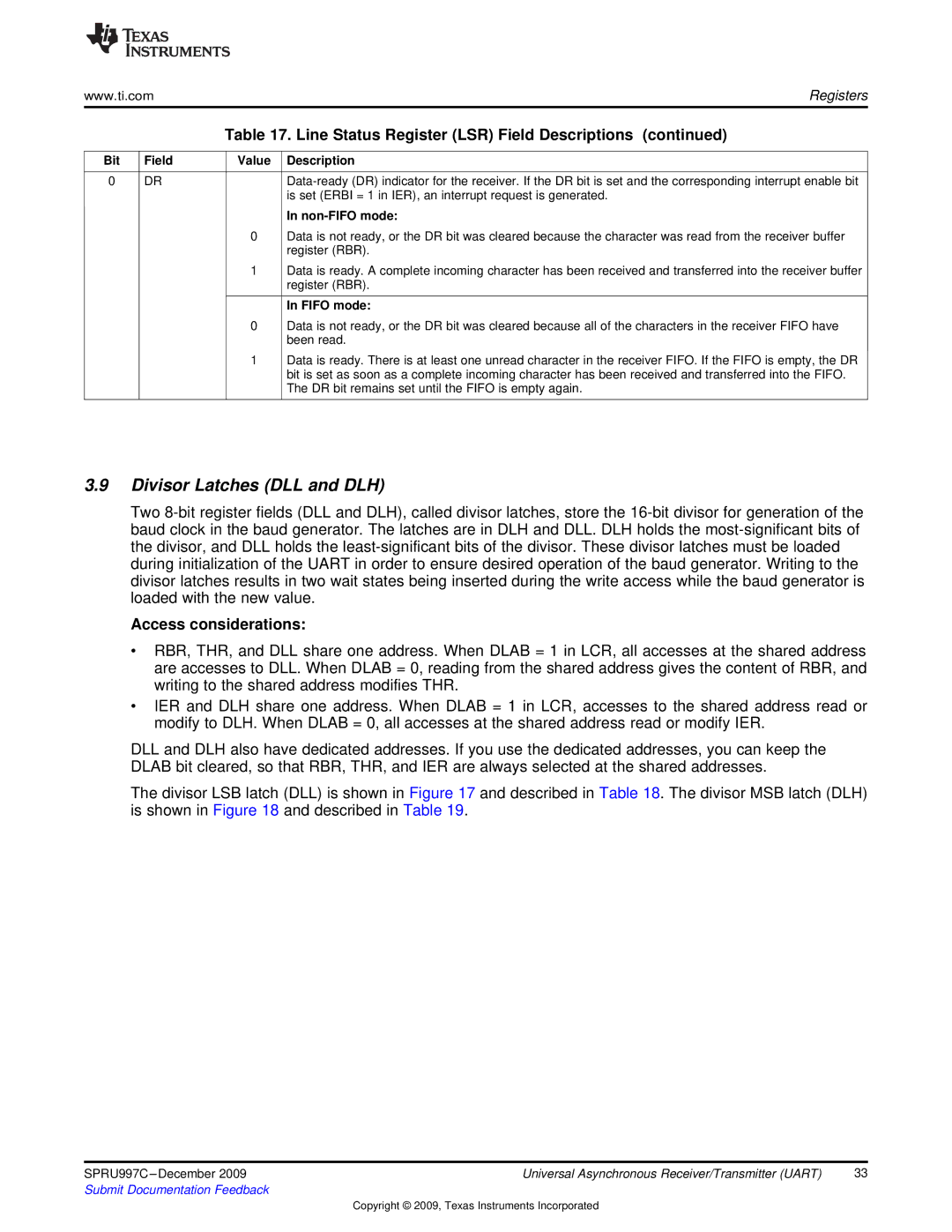
Table 17. Line Status Register (LSR) Field Descriptions (continued)
Bit | Field | Value | Description |
|
|
|
|
0 | DR |
| |
|
|
| is set (ERBI = 1 in IER), an interrupt request is generated. |
|
|
| In |
|
| 0 | Data is not ready, or the DR bit was cleared because the character was read from the receiver buffer |
|
|
| register (RBR). |
|
| 1 | Data is ready. A complete incoming character has been received and transferred into the receiver buffer |
|
|
| register (RBR). |
|
|
|
|
|
|
| In FIFO mode: |
|
| 0 | Data is not ready, or the DR bit was cleared because all of the characters in the receiver FIFO have |
|
|
| been read. |
|
| 1 | Data is ready. There is at least one unread character in the receiver FIFO. If the FIFO is empty, the DR |
|
|
| bit is set as soon as a complete incoming character has been received and transferred into the FIFO. |
|
|
| The DR bit remains set until the FIFO is empty again. |
|
|
|
|
3.9Divisor Latches (DLL and DLH)
Two
Access considerations:
•RBR, THR, and DLL share one address. When DLAB = 1 in LCR, all accesses at the shared address are accesses to DLL. When DLAB = 0, reading from the shared address gives the content of RBR, and writing to the shared address modifies THR.
•IER and DLH share one address. When DLAB = 1 in LCR, accesses to the shared address read or modify to DLH. When DLAB = 0, all accesses at the shared address read or modify IER.
DLL and DLH also have dedicated addresses. If you use the dedicated addresses, you can keep the DLAB bit cleared, so that RBR, THR, and IER are always selected at the shared addresses.
The divisor LSB latch (DLL) is shown in Figure 17 and described in Table 18. The divisor MSB latch (DLH) is shown in Figure 18 and described in Table 19.
SPRU997C | Universal Asynchronous Receiver/Transmitter (UART) | 33 |
Submit Documentation Feedback |
|
|
Copyright © 2009, Texas Instruments Incorporated