www.ti.com | Peripheral Architecture |
2.6.4.1RTS Behavior
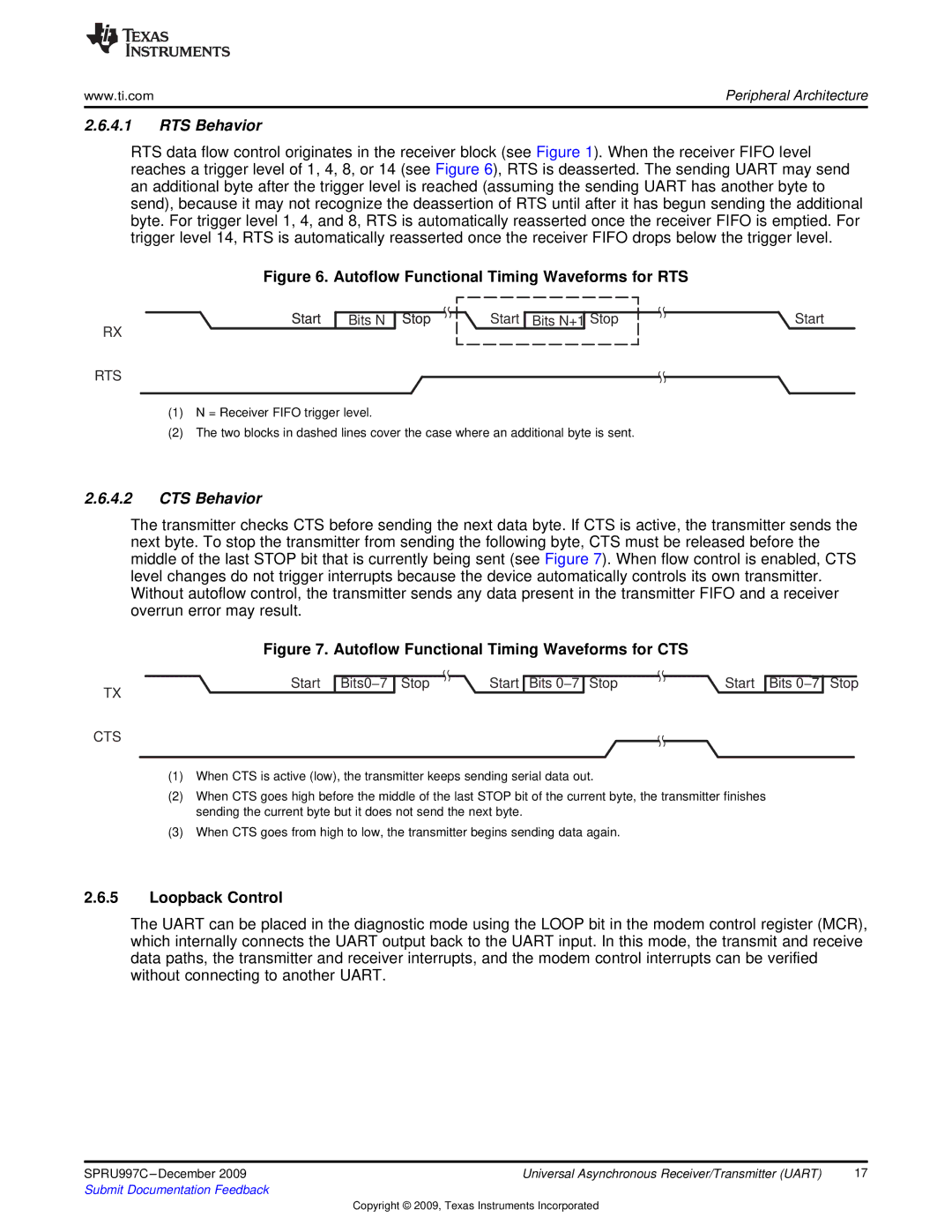
RTS data flow control originates in the receiver block (see Figure 1). When the receiver FIFO level reaches a trigger level of 1, 4, 8, or 14 (see Figure 6), RTS is deasserted. The sending UART may send an additional byte after the trigger level is reached (assuming the sending UART has another byte to send), because it may not recognize the deassertion of RTS until after it has begun sending the additional byte. For trigger level 1, 4, and 8, RTS is automatically reasserted once the receiver FIFO is emptied. For trigger level 14, RTS is automatically reasserted once the receiver FIFO drops below the trigger level.
Figure 6. Autoflow Functional Timing Waveforms for RTS
Start
RX
RTS
Bits N
Stop | Start Bits N+1 Stop | Start |
(1)N = Receiver FIFO trigger level.
(2)The two blocks in dashed lines cover the case where an additional byte is sent.
2.6.4.2CTS Behavior
The transmitter checks CTS before sending the next data byte. If CTS is active, the transmitter sends the next byte. To stop the transmitter from sending the following byte, CTS must be released before the middle of the last STOP bit that is currently being sent (see Figure 7). When flow control is enabled, CTS level changes do not trigger interrupts because the device automatically controls its own transmitter. Without autoflow control, the transmitter sends any data present in the transmitter FIFO and a receiver overrun error may result.
Figure 7. Autoflow Functional Timing Waveforms for CTS
Start Bits0−7 Stop | Start Bits 0−7 Stop | Start |
TX
CTS
Bits 0−7
Stop
(1)When CTS is active (low), the transmitter keeps sending serial data out.
(2)When CTS goes high before the middle of the last STOP bit of the current byte, the transmitter finishes sending the current byte but it does not send the next byte.
(3)When CTS goes from high to low, the transmitter begins sending data again.
2.6.5Loopback Control
The UART can be placed in the diagnostic mode using the LOOP bit in the modem control register (MCR), which internally connects the UART output back to the UART input. In this mode, the transmit and receive data paths, the transmitter and receiver interrupts, and the modem control interrupts can be verified without connecting to another UART.
SPRU997C | Universal Asynchronous Receiver/Transmitter (UART) | 17 |
Submit Documentation Feedback |
|
|
Copyright © 2009, Texas Instruments Incorporated