www.ti.com | Registers |
3.8Line Status Register (LSR)
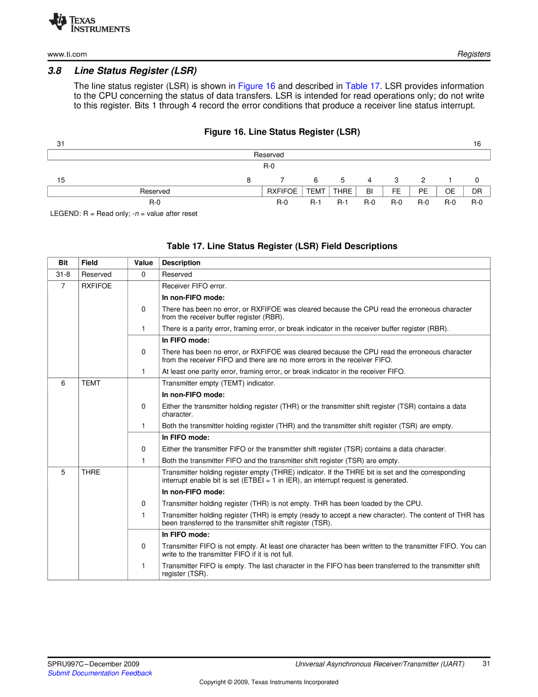
The line status register (LSR) is shown in Figure 16 and described in Table 17. LSR provides information to the CPU concerning the status of data transfers. LSR is intended for read operations only; do not write to this register. Bits 1 through 4 record the error conditions that produce a receiver line status interrupt.
Figure 16. Line Status Register (LSR)
31 |
|
|
|
|
|
|
|
|
| 16 |
|
| Reserved |
|
|
|
|
|
|
| |
|
|
|
|
|
|
|
|
|
| |
15 | 8 | 7 | 6 | 5 | 4 | 3 | 2 | 1 | 0 | |
|
|
|
|
|
|
|
|
|
|
|
Reserved |
|
| RXFIFOE | TEMT | THRE | BI | FE | PE | OE | DR |
|
|
|
|
|
|
|
|
|
|
|
|
| |||||||||
LEGEND: R = Read only; |
|
|
|
|
|
|
|
|
|
|
|
|
| Table 17. Line Status Register (LSR) Field Descriptions |
|
|
|
|
Bit | Field | Value | Description |
|
|
|
|
Reserved | 0 | Reserved | |
|
|
|
|
7 | RXFIFOE |
| Receiver FIFO error. |
|
|
| In |
|
| 0 | There has been no error, or RXFIFOE was cleared because the CPU read the erroneous character |
|
|
| from the receiver buffer register (RBR). |
|
| 1 | There is a parity error, framing error, or break indicator in the receiver buffer register (RBR). |
|
|
|
|
|
|
| In FIFO mode: |
|
| 0 | There has been no error, or RXFIFOE was cleared because the CPU read the erroneous character |
|
|
| from the receiver FIFO and there are no more errors in the receiver FIFO. |
|
| 1 | At least one parity error, framing error, or break indicator in the receiver FIFO. |
|
|
|
|
6 | TEMT |
| Transmitter empty (TEMT) indicator. |
|
|
| In |
|
| 0 | Either the transmitter holding register (THR) or the transmitter shift register (TSR) contains a data |
|
|
| character. |
|
| 1 | Both the transmitter holding register (THR) and the transmitter shift register (TSR) are empty. |
|
|
|
|
|
|
| In FIFO mode: |
|
| 0 | Either the transmitter FIFO or the transmitter shift register (TSR) contains a data character. |
|
| 1 | Both the transmitter FIFO and the transmitter shift register (TSR) are empty. |
|
|
|
|
5 | THRE |
| Transmitter holding register empty (THRE) indicator. If the THRE bit is set and the corresponding |
|
|
| interrupt enable bit is set (ETBEI = 1 in IER), an interrupt request is generated. |
|
|
| In |
|
| 0 | Transmitter holding register (THR) is not empty. THR has been loaded by the CPU. |
|
| 1 | Transmitter holding register (THR) is empty (ready to accept a new character). The content of THR has |
|
|
| been transferred to the transmitter shift register (TSR). |
|
|
|
|
|
|
| In FIFO mode: |
|
| 0 | Transmitter FIFO is not empty. At least one character has been written to the transmitter FIFO. You can |
|
|
| write to the transmitter FIFO if it is not full. |
|
| 1 | Transmitter FIFO is empty. The last character in the FIFO has been transferred to the transmitter shift |
|
|
| register (TSR). |
|
|
|
|
SPRU997C | Universal Asynchronous Receiver/Transmitter (UART) | 31 |
Submit Documentation Feedback |
|
|
Copyright © 2009, Texas Instruments Incorporated